Contents
SD-WAN interfaces
SD-WAN interfaces (hereinafter also referred to as simply 'interfaces') are logical interfaces for building an SD-WAN network topology. These interfaces have predefined types and are associated with network interfaces (the mapping is based on the alias of the network interface).
When you create an SD-WAN interface, an OpenFlow interface is automatically created for it with a number specified by you. Kaspersky SD-WAN temporarily supports creating only WAN interfaces.
By default, the solution has two SD-WAN interfaces created, and you can change their settings if necessary.
Providing information about WAN interfaces to the SD-WAN Controller
Providing public IP addresses and UDP ports of WAN interfaces to the SD-WAN Controller
To build GENEVE tunnels between CPE devices, the SD-WAN Controller must obtain information about the public IP addresses of the WAN interfaces of these devices. By default, the controller receives this information through an OpenFlow TCP session that is established between the device and the Controller. In that case, the source IP address is used as the public IP address.
If the SD-WAN Controller is unable to obtain the information it needs, you can manually specify the IP addresses and UDP ports of the WAN interfaces of CPE devices. In the figure below, CPE 1 and the SD-WAN Controller are on the same local network and gain access to the Internet through the same firewall that does IP address forwarding. When establishing a session between the WAN interface of CPE 1 and the public IP address of the SD-WAN Controller (10.0.1.1 > 1.1.1.2), if the firewall cannot be configured in a way that would involve the Controller forwarding the private IP address to the public IP address (10.0.1.1 > 1.1.1.1), the Controller is unable to obtain information about the public IP address of the WAN interface and provide it to other devices in the topology (CPE 2). As a result, a GENEVE tunnel cannot be created between CPE 1 and CPE 2; CPE 1 becomes isolated and cannot be added to the common
.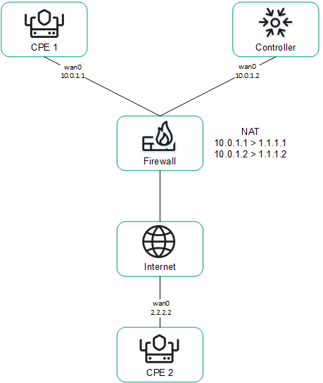
CPE 1 and the Controller are behind NAT and are connected to CPE 2
Providing IP addresses of WAN interfaces from an isolated network to the SD-WAN Controller
Some of the WAN interfaces of a CPE device may be on an isolated network without the possibility of establishing a TCP session with the SD-WAN Controller, but they can be used to build GENEVE tunnels. In this case, the Controller cannot obtain information about the IP addresses of isolated WAN interfaces and use it to build GENEVE tunnels between CPE devices.
In the figure below, CPE 1 and CPE 2 have two WAN interfaces each, but they can establish communication with the SD-WAN Controller only through their wan0 interfaces because the wan1 interfaces are on an isolated network (MPLS) that does not have access to the Controller. However, both wan1 interfaces can be used to build GENEVE tunnels.
Please note that if the communication channel used to interact with the SD-WAN Controller fails for one of the CPE devices, all other communication channels also cannot be used, even if they remain operational, because the Controller eliminates the device from the topology.
The IP addresses of the isolated WAN interfaces can be provided to the SD-WAN Controller through the orchestrator.
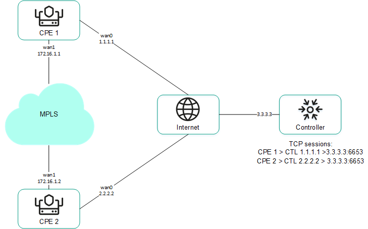
CPE 1 and CPE 2 are connected with each other through MPLS and with the SD-WAN Controller through the Internet.
You can configure the sending of the necessary information when creating or editing the SD-WAN interface.
Page topOverriding the IP address and port for connecting an interface to the SD-WAN controller
You can connect WAN interfaces to the SD-WAN Controller even if they use different types of communication channels, for example, the Internet vs a private MPLS network (see the figure below). In this case, you need to manually override IP addresses and ports for connecting to the Controller when creating or editing interfaces.

Connecting the CPE device to the Controller via two different communication channels
If your SD-WAN instance uses multiple Controller nodes, you must override IP addresses for all nodes. If the number of SD-WAN Controller nodes does not match the number of specified IP addresses, an error occurs and the values stay the same.
After overriding the IP address and port for connecting the interface to the SD-WAN Controller, you must restart the CPE device.
Page topCreating an SD-WAN interface
You can create an SD-WAN interface on an individual CPE device or on all devices that use the CPE template. SD-WAN interfaces are created on top of network interfaces, so you must first create a network interface.
To create an SD-WAN interface, use the following instructions:
- Creating an SD-WAN interface on an individual CPE device.
To create an SD-WAN interface on an individual CPE device:
- In the menu, go to the SD-WAN section.
By default, the CPE subsection is displayed with a table of CPE devices.
- Click the CPE device.
The settings area is displayed in the lower part of the page. You can expand the settings area to fill the entire page by clicking the expand button
 .
. - Select the SD-WAN settings → Interfaces tab.
A table of SD-WAN interfaces is displayed.
- Click + SD-WAN interface.
- This opens a window; in that window, in the OpenFlow interface field, enter the number of the OpenFlow interface that must be created on the virtual switch of the CPE device.
- In the Interface (alias) field, enter the alias of the network interface to which you want to bind the OpenFlow interface.
- In the Maximum rate field, enter the maximum speed of the SD-WAN interface in Mbps. Range of values: 1 to 100,000. The default setting is
1,000. - Specify the host whose availability determines the availability of the SD-WAN interface:
- In the IP for tracking field, enter the IP address of the host.
- Click + Add.
You can specify multiple hosts.
- In the Reliability field, enter the number of hosts that must remain available for the SD-WAN interface to be considered available. The default setting is
1.Make sure that the number of hosts does not exceed the number of IP addresses in the IP for tracking field. Otherwise, the SD-WAN interface will always be considered unavailable.
- In the Interval field, enter the SD-WAN interface testing interval in seconds. Range of values: 1 to 600. The default setting is
2. - In the Count field, enter the number of availability checks for each of the specified hosts as part of a single SD-WAN interface test. Range of values: 1 to 600. The default setting is
2. - In the Timeout field, enter the time in milliseconds for the SD-WAN interface to wait for an echo response from the hosts after sending an echo request. Range of values: 1 to 100,000. The default setting is
2000. - In the Down field, enter the interval in seconds for testing the SD-WAN interface if it becomes unavailable. Range of values: 1 to 600. The default setting is
3. - In the Up field, enter the interval in seconds for testing the SD-WAN interface if it becomes available again. Range of values: 1 to 600. The default setting is
2. - In the Speed monitoring drop-down list, select whether to check the speed limit of the SD-WAN interface imposed by the mobile operator:
- Yes
- No (selected by default)
- If necessary, configure traffic queues on the SD-WAN interface:
- Select the QoS tab.
A table of traffic queues is displayed.
- In the Remap ToS column, select the Type of Service value of external headers of traffic packets for each queue. You cannot select these values when configuring traffic queues for the LAN interface.
- In the Minimum Speed, % column, specify the minimum traffic bandwidth for the queue as a percentage of the maximum speed of the SD-WAN interface. The sum total in a column may not exceed 100.
- In the Maximum Speed, % column, specify the maximum traffic bandwidth for the queue as a percentage of the maximum speed of the SD-WAN interface. This setting is used to prevent traffic of high-priority queues from indefinitely preempting traffic of low-priority queues.
The maximum speed of the interface is specified when configuring the connection of the CPE device to the SD-WAN network on the General settings tab in the Maximum rate field.
- Select the QoS tab.
- If necessary, configure the sending of interface information to the SD-WAN Controller:
- Select the NAT and Disjoint WAN underlay tab.
- In the State drop-down list, select one of the following values:
- Disabled if the SD-WAN Controller does not need to receive information about the interface.
- NAT/PAT if the interface is behind NAT or PAT and needs to be assigned a public IP address and UDP port number, which must be sent to the SD-WAN Controller.
- Disjoint WAN Underlay if the interface is on an isolated network and its IP address must be sent to the SD-WAN Controller.
- If in the State drop-down list, you selected NAT/PAT, follow these steps:
- In the Real IP Address field, enter the public IP address (IPv4) of the interface.
- In the Real GENEVE UDP Port field, enter the UDP port number of the interface. Range of values: 1 to 65,353.
- If in the State drop-down list, you selectedDisjoint WAN Underlay, in the IP address field, enter the IP address (IPv4) of the interface. You must enter the IP address specified when creating the network interface over which the SD-WAN interface is created.
- If necessary, override the IP address and port for connecting the interface to the SD-WAN Controller:
- Select the Controllers tab.
- Select the Rewrite controllers IP/Port check box. This check box is cleared by default.
- In the Controllers QTY drop-down list, select the number of Controller nodes in your SD-WAN instance.
You must override the IP address for connecting the interface to each node of the SD-WAN Controller. Otherwise, an error occurs and the settings remain unchanged.
- In the Port field, enter the starting port number for connecting the interface to the SD-WAN Controller. The number of fields corresponds to the value that you selected in the Controllers QTY drop-down list. Range of values: 1 to 65,535. The default setting is
6653.The starting port is used to configure the ports for connecting to the SD-WAN Controller. The number of configured ports depends on the number of WAN interfaces of the CPE device. For example, if you enter
6653as the starting port number and the device has four WAN interfaces, port numbers 6654, 6655, and 6656 are derived from that port. - In the IP address field, enter the IP address (IPv4) for connecting the interface to the SD-WAN Controller. The number of fields corresponds to the value that you selected in the Controllers QTY drop-down list.
After overriding the IP address and port for connecting the interface to the SD-WAN Controller, you must restart the CPE device.
- Click Create.
The SD-WAN interface is created and displayed in the table.
- In the upper part of the settings area, click Save to save the configuration of the CPE device.
- In the menu, go to the SD-WAN section.
- Creating an SD-WAN interface on all devices that use the CPE template.
To create an SD-WAN interface on all devices that use the CPE template:
- In the menu, go to the SD-WAN → CPE templates subsection.
A table of CPE templates is displayed.
- Click the CPE template.
The settings area is displayed in the lower part of the page. You can expand the settings area to fill the entire page by clicking the expand button
. - Select the SD-WAN settings → Interfaces tab.
A table of SD-WAN interfaces is displayed.
- Click + SD-WAN interface.
- This opens a window; in that window, in the OpenFlow interface field, enter the number of the OpenFlow interface that must be created on the virtual switch of the CPE device.
- In the Interface (alias) field, enter the alias of the network interface to which you want to bind the OpenFlow interface.
- In the Maximum rate field, enter the maximum speed of the SD-WAN interface in Mbps. Range of values: 1 to 100,000. The default setting is
1,000. - Specify the host whose availability determines the availability of the SD-WAN interface:
- In the IP for tracking field, enter the IP address of the host.
- Click + Add.
You can specify multiple hosts.
- In the Reliability field, enter the number of hosts that must remain available for the SD-WAN interface to be considered available. The default setting is
1.Make sure that the number of hosts does not exceed the number of IP addresses in the IP for tracking field. Otherwise, the SD-WAN interface will always be considered unavailable.
- In the Interval field, enter the SD-WAN interface testing interval in seconds. Range of values: 1 to 600. The default setting is
2. - In the Count field, enter the number of availability checks for each of the specified hosts as part of a single SD-WAN interface test. Range of values: 1 to 600. The default setting is
2. - In the Timeout field, enter the time in milliseconds for the SD-WAN interface to wait for an echo response from the hosts after sending an echo request. Range of values: 1 to 100,000. The default setting is
2000. - In the Down field, enter the interval in seconds for testing the SD-WAN interface if it becomes unavailable. Range of values: 1 to 600. The default setting is
3. - In the Up field, enter the interval in seconds for testing the SD-WAN interface if it becomes available again. Range of values: 1 to 600. The default setting is
2. - In the Speed monitoring drop-down list, select whether to check the speed limit of the SD-WAN interface imposed by the mobile operator:
- Yes
- No (selected by default)
- If necessary, configure traffic queues on the SD-WAN interface:
- Select the QoS tab.
A table of traffic queues is displayed.
- In the Remap ToS column, select the Type of Service value of external headers of traffic packets for each queue. You cannot select these values when configuring traffic queues for the LAN interface.
- In the Minimum Speed, % column, specify the minimum traffic bandwidth for the queue as a percentage of the maximum speed of the SD-WAN interface. The sum total in a column may not exceed 100.
- In the Maximum Speed, % column, specify the maximum traffic bandwidth for the queue as a percentage of the maximum speed of the SD-WAN interface. This setting is used to prevent traffic of high-priority queues from indefinitely preempting traffic of low-priority queues.
The maximum speed of the interface is specified when configuring the connection of the CPE device to the SD-WAN network on the General settings tab in the Maximum rate field.
- Select the QoS tab.
- If necessary, configure the sending of interface information to the SD-WAN Controller:
- Select the NAT and Disjoint WAN underlay tab.
- In the State drop-down list, select one of the following values:
- Disabled if the SD-WAN Controller does not need to receive information about the interface.
- NAT/PAT if the interface is behind NAT or PAT and needs to be assigned a public IP address and UDP port number, which must be sent to the SD-WAN Controller.
- Disjoint WAN Underlay if the interface is on an isolated network and its IP address must be sent to the SD-WAN Controller.
- If in the State drop-down list, you selected NAT/PAT, follow these steps:
- In the Real IP Address field, enter the public IP address (IPv4) of the interface.
- In the Real GENEVE UDP Port field, enter the UDP port number of the interface. Range of values: 1 to 65,353.
- If in the State drop-down list, you selectedDisjoint WAN Underlay, in the IP address field, enter the IP address (IPv4) of the interface. You must enter the IP address specified when creating the network interface over which the SD-WAN interface is created.
- If necessary, override the IP address and port for connecting the interface to the SD-WAN Controller:
- Select the Controllers tab.
- Select the Rewrite controllers IP/Port check box. This check box is cleared by default.
- In the Controllers QTY drop-down list, select the number of Controller nodes in your SD-WAN instance.
You must override the IP address for connecting the interface to each node of the SD-WAN Controller. Otherwise, an error occurs and the settings remain unchanged.
- In the Port field, enter the starting port number for connecting the interface to the SD-WAN Controller. The number of fields corresponds to the value that you selected in the Controllers QTY drop-down list. Range of values: 1 to 65,535. The default setting is
6653.The starting port is used to configure the ports for connecting to the SD-WAN Controller. The number of configured ports depends on the number of WAN interfaces of the CPE device. For example, if you enter
6653as the starting port number and the device has four WAN interfaces, port numbers 6654, 6655, and 6656 are derived from that port. - In the IP address field, enter the IP address (IPv4) for connecting the interface to the SD-WAN Controller. The number of fields corresponds to the value that you selected in the Controllers QTY drop-down list.
After overriding the IP address and port for connecting the interface to the SD-WAN Controller, you must restart the CPE device.
- Click Create.
The SD-WAN interface is created and displayed in the table.
- In the upper part of the settings area, click Save to save the configuration of the CPE template.
- In the menu, go to the SD-WAN → CPE templates subsection.
Editing an SD-WAN interface
You can edit an SD-WAN interface on an individual CPE device or on all devices that use the CPE template. For a description of the settings, see the instructions for creating an SD-WAN interface.
To edit an SD-WAN interface on an individual CPE device:
- In the menu, go to the SD-WAN section.
By default, the CPE subsection is displayed with a table of CPE devices.
- Click the CPE device.
The settings area is displayed in the lower part of the page. You can expand the settings area to fill the entire page by clicking the expand button
. - Select the SD-WAN settings → Interfaces tab.
A table of SD-WAN interfaces is displayed.
- Select the Override check box next to the SD-WAN interface to ignore the applied CPE template and be able to edit the interface settings. This check box is cleared by default.
- Click Edit.
- This opens a window; in that window, edit the settings of the SD-WAN interface that you want to change:
- Click Save.
- In the upper part of the settings area, click Save to save the configuration of the CPE device.
To edit an SD-WAN interface on all devices that use the CPE template:
- In the menu, go to the SD-WAN → CPE templates subsection.
A table of CPE templates is displayed.
- Click the CPE template.
The settings area is displayed in the lower part of the page. You can expand the settings area to fill the entire page by clicking the expand button
. - Select the SD-WAN settings → Interfaces tab.
A table of SD-WAN interfaces is displayed.
- Click Edit next to the SD-WAN interface.
- This opens a window; in that window, edit the settings of the SD-WAN interface that you want to change:
- Click Save.
- In the upper part of the settings area, click Save to save the configuration of the CPE template.
Disabling an SD-WAN interface
You can disable an SD-WAN interface on an individual CPE device or on all devices that use the CPE template.
To disable an SD-WAN interface on an individual CPE device:
- In the menu, go to the SD-WAN section.
By default, the CPE subsection is displayed with a table of CPE devices.
- Click the CPE device.
The settings area is displayed in the lower part of the page. You can expand the settings area to fill the entire page by clicking the expand button
. - Select the SD-WAN settings → Interfaces tab.
A table of SD-WAN interfaces is displayed.
- Select the Override check box next to the SD-WAN interface to ignore the applied CPE template and be able to disable the interface. This check box is cleared by default.
- Click Disable.
- In the upper part of the settings area, click Save to save the configuration of the CPE device.
To disable an SD-WAN interface on all devices that use the CPE template:
- In the menu, go to the SD-WAN → CPE templates subsection.
A table of CPE templates is displayed.
- Click the CPE template.
The settings area is displayed in the lower part of the page. You can expand the settings area to fill the entire page by clicking the expand button
. - Select the SD-WAN settings → Interfaces tab.
A table of SD-WAN interfaces is displayed.
- Click Disable next to the SD-WAN interface.
- In the upper part of the settings area, click Save to save the configuration of the CPE template.
Deleting an SD-WAN interface
You can delete an SD-WAN interface on an individual CPE device or on all devices that use the CPE template. On an individual CPE device, you can delete only those SD-WAN interfaces that were created locally and not the ones that were inherited from the template. Deleted SD-WAN interfaces cannot be restored.
To delete a network interface on an individual CPE device:
- In the menu, go to the SD-WAN section.
By default, the CPE subsection is displayed with a table of CPE devices.
- Click the CPE device.
The settings area is displayed in the lower part of the page. You can expand the settings area to fill the entire page by clicking the expand button
. - Select the SD-WAN settings → Interfaces tab.
A table of SD-WAN interfaces is displayed.
- Click Delete next to the SD-WAN interface.
- In the confirmation window, click Delete.
The SD-WAN interface is deleted and is no longer displayed in the table.
To delete an SD-WAN interface on all devices that use the CPE template:
- In the menu, go to the SD-WAN → CPE templates subsection.
A table of CPE templates is displayed.
- Click the CPE template.
The settings area is displayed in the lower part of the page. You can expand the settings area to fill the entire page by clicking the expand button
. - Select the SD-WAN settings → Interfaces tab.
A table of SD-WAN interfaces is displayed.
- Click Delete next to the SD-WAN interface.
- In the confirmation window, click Delete.
The SD-WAN interface is deleted and is no longer displayed in the table.
Page top