Managing virtual routing and forwarding (VRF) tables
Kaspersky SD-WAN supports the Virtual Routing and Forwarding (VRF) technology for creating virtual routing and forwarding tables on CPE devices. You can create up to 100 virtual routing and forwarding tables.
When creating a virtual routing and forwarding table, you must select network interfaces that you want to add to it. You cannot add the same network interface to multiple virtual routing and forwarding tables. Network interfaces for connecting the CPE device to the controller and orchestrator are automatically added to the default virtual routing and forwarding table and you cannot add them to other virtual routing and forwarding tables.
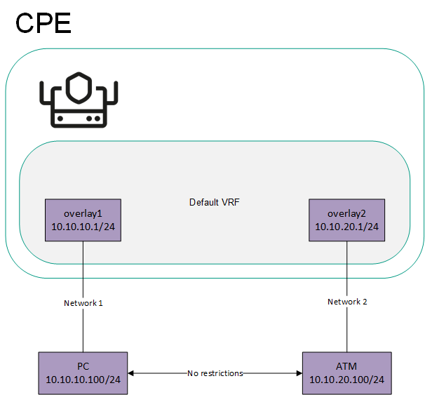
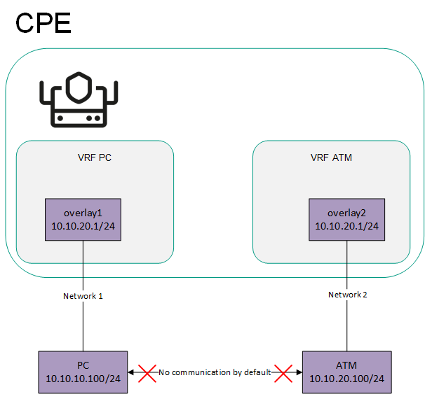
If network interfaces are added to different virtual routing and forwarding tables, networks connected to these network interfaces do not have access to each other. In this situation, network interfaces can have IP addresses from identical or overlapping subnets.
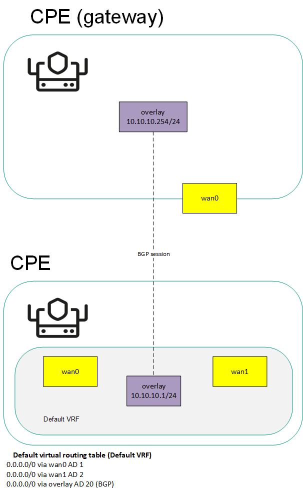
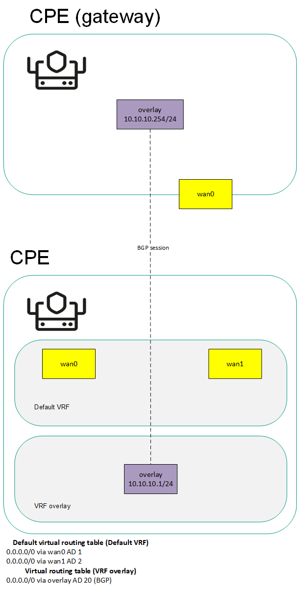
When you create a virtual routing and forwarding table, a system network interface corresponding to this virtual routing and forwarding table is automatically created on the CPE device. This system network interface is used to forward traffic between network interfaces in the virtual routing and forwarding table. For the system network interface to work, you need to create a record for it in the orchestrator web interface.
If no firewall zones are assigned to network interfaces in the virtual routing and forwarding table, you need to make sure that by default, the firewall of the CPE device accepts traffic packets forwarded between network interfaces and subnets. You can specify default actions when configuring the basic settings of the firewall.
If firewall zones are assigned to network interfaces in the virtual routing and forwarding table, and the CPE device firewall does not, by default, accept traffic packets forwarded between network interfaces and subnets, you must assign a firewall zone to the system network interface. The assigned firewall zone must also be assigned to one of the network interfaces in the virtual routing and forwarding table.
You can add BGP routes and static routes to virtual routing and forwarding tables of a CPE device. To add BGP routes to a virtual routing and forwarding table, specify that virtual routing and forwarding table when editing basic BGP settings. To add a static route to a virtual routing and forwarding table, specify that virtual routing and forwarding table when adding the static route.
You can use virtual routing and forwarding tables in the following scenarios:
The table of virtual routing and forwarding tables is displayed in the CPE template and on the CPE device:
- To display the table of virtual routing and forwarding tables in a CPE template, go to the SD-WAN → CPE templates menu section, click the CPE template, and select the VRF tab.
- To display the table of virtual routing and forwarding tables on a CPE device, go to the SD-WAN → CPE menu section, click the CPE device, and select the VRF tab.
Information about virtual routing and forwarding tables is displayed in the following columns of the table:
- Name is the name of the virtual routing and forwarding table.
- Table is the ID of the virtual routing and forwarding table.
- Interfaces are network interfaces that have been added to the virtual routing and forwarding table.