Contents
About Kaspersky SD-WAN
Kaspersky SD-WAN is used to build Software-Defined Wide Area Networks (Software Defined WAN; SD-WAN). In such networks, routes with the lowest latency and the greatest bandwidth are determined automatically. Traffic is routed using the SDN (Software Defined Networking) technology.
The SDN technology separates the
from the and allows managing the network infrastructure using an and the API. Separating the control plane from the data plane makes it possible to virtualize network functions (Network Function Virtualization; NFV), wherein network functions such as firewalls, routers, and load balancers are deployed on standard equipment. Network function virtualization in the solution is compliant with the NFV MANO specification (NFV Management and Network Orchestration) standards of the European Telecommunications Standards Institute (ETSI).Building an SD-WAN network does not depend on transport technologies. You can also send traffic over multiple links based on application requirements regarding bandwidth and quality of service. The following underlay network types are supported:
- MPLS transport networks
- Broadband links for connecting to the Internet
- Leased communication lines
- Wireless connections including 3G, 4G, and LTE
- Satellite links
Kaspersky SD-WAN lets you do the following:
- Intelligent traffic management
- Automatic CPE device configuration
- Central management of solution components using the web interface
- Network monitoring
- Automatically responding to changes in QoS policies to meet requirements of applications
The figure below shows a diagram of an SD-WAN network built using the Kaspersky SD-WAN solution.
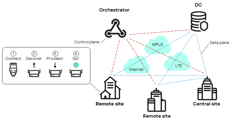
SD-WAN network diagram
Distribution kit
To learn more about purchasing the solution, please visit the Kaspersky website (https://www.kaspersky.com) or contact partner companies.
The distribution kit includes the following components:
- knaas-installer_<version> in the TAR.GZ format (hereinafter also referred to as the installation archive) for solution deployment.
- Docker containers for deploying Kaspersky SD-WAN components:
- knaas-ctl
- knaas-orc
- knaas-www
- knass-vnfm
- knaas-vnfm-proxy
- mockpnf
You must download the following containers from the common Docker repository:
- mariaDB
- mongo
- redis
- syslog-ng
- zabbix-proxy-mysql
- zabbix-server-mysql
- zabbix-web-nginx-mysql
- CPE device firmware.
- A file with the text of the End User License Agreement, which stipulates the terms and conditions that you must accept to use the solution.
- Kaspersky SD-WAN Online Help files that let you read documentation without an Internet connection.
The content of the distribution kit may differ depending on the region in which the solution is distributed.
Page topHardware and software requirements
Kaspersky SD-WAN has the following hardware and software requirements:
Hardware requirements depend on the number of CPE devices being managed (see the table below). If you need to connect more than 250 CPE devices, you need to deploy additional controllers. If you need to calculate hardware requirements for a specific deployment scheme more precisely, we recommend contacting Kaspersky Technical Support.
Component |
RAM, GB |
Virtual CPU |
Disk, GB |
IOPS |
50 CPE devices |
||||
Redis replica server |
1 |
2 |
100 |
1000 |
Redis Sentinel system |
1 |
2 |
||
MongoDB database |
2 |
2 |
||
Orchestrator |
4 |
4 |
||
Virtual Network Function Manager (VNFM) |
1 |
2 |
||
Proxy Virtual Network Function Manager (VNFM proxy) |
1 |
2 |
||
Frontend part of the solution |
1 |
2 |
||
Database of the Zabbix monitoring system |
1 |
2 |
500 |
1000 |
Zabbix server |
1 |
2 |
||
Frontend part of the Zabbix monitoring system |
1 |
2 |
||
Zabbix proxy server |
1 |
2 |
||
Syslog server |
1 |
1 |
No value |
No value |
Data storage system |
8 |
8 |
20 |
1000 |
Controller |
8 |
8 |
64 |
1000 |
100 CPE devices |
||||
Redis replica server |
1 |
2 |
100 |
1000 |
Redis Sentinel system |
1 |
2 |
||
MongoDB database |
4 |
4 |
||
Orchestrator |
4 |
4 |
||
Virtual Network Function Manager (VNFM) |
1 |
2 |
||
Proxy Virtual Network Function Manager (VNFM proxy) |
1 |
2 |
||
Frontend part of the solution |
2 |
2 |
||
Database of the Zabbix monitoring system |
1 |
4 |
1000 |
1000 |
Zabbix server |
1 |
2 |
||
Frontend part of the Zabbix monitoring system |
1 |
2 |
||
Zabbix proxy server |
1 |
2 |
||
Syslog server |
1 |
2 |
No value |
No value |
Data storage system |
8 |
8 |
20 |
1000 |
Controller |
8 |
8 |
64 |
1000 |
250 CPE devices |
||||
Redis replica server |
2 |
2 |
100 |
1000 |
Redis Sentinel system |
2 |
2 |
||
MongoDB database |
4 |
4 |
||
Orchestrator |
4 |
6 |
||
Virtual Network Function Manager (VNFM) |
2 |
2 |
||
Proxy Virtual Network Function Manager (VNFM proxy) |
2 |
2 |
||
Frontend part of the solution |
2 |
2 |
||
Database of the Zabbix monitoring system |
2 |
4 |
2500 |
1000 |
Zabbix server |
2 |
4 |
||
Frontend part of the Zabbix monitoring system |
2 |
2 |
||
Zabbix proxy server |
2 |
2 |
||
Syslog server |
2 |
2 |
No value |
No value |
Data storage system |
10 |
8 |
20 |
1000 |
Controller |
16 |
8 |
64 |
1000 |
500 CPE devices |
||||
Redis replica server |
2 |
2 |
100 |
1000 |
Redis Sentinel system |
2 |
2 |
||
MongoDB database |
4 |
6 |
||
Orchestrator |
6 |
6 |
||
Virtual Network Function Manager (VNFM) |
2 |
2 |
||
Proxy Virtual Network Function Manager (VNFM proxy) |
2 |
2 |
||
Frontend part of the solution |
2 |
2 |
||
Database of the Zabbix monitoring system |
2 |
4 |
5000 |
1000 |
Zabbix server |
2 |
4 |
||
Frontend part of the Zabbix monitoring system |
2 |
4 |
||
Zabbix proxy server |
2 |
4 |
||
Syslog server |
2 |
2 |
No value |
No value |
Data storage system |
10 |
8 |
20 |
1000 |
Controller |
32 |
8 |
128 |
1000 |
1000 CPE devices |
||||
Redis replica server |
2 |
4 |
100 |
1000 |
Redis Sentinel system |
2 |
2 |
||
MongoDB database |
6 |
6 |
||
Orchestrator |
8 |
6 |
||
Virtual Network Function Manager (VNFM) |
2 |
2 |
||
Proxy Virtual Network Function Manager (VNFM proxy) |
2 |
2 |
||
Frontend part of the solution |
2 |
2 |
||
Database of the Zabbix monitoring system |
2 |
6 |
1000 |
1000 |
Zabbix server |
2 |
6 |
||
Frontend part of the Zabbix monitoring system |
2 |
4 |
||
Zabbix proxy server |
2 |
4 |
||
Syslog server |
2 |
6 |
No value |
No value |
Data storage system |
12 |
10 |
20 |
1000 |
Controller |
64 |
8 |
256 |
1000 |
2000 CPE devices |
||||
Redis replica server |
4 |
4 |
200 |
2000 |
Redis Sentinel system |
4 |
2 |
||
MongoDB database |
8 |
6 |
||
Orchestrator |
10 |
6 |
||
Virtual Network Function Manager (VNFM) |
4 |
2 |
||
Proxy Virtual Network Function Manager (VNFM proxy) |
4 |
2 |
||
Frontend part of the solution |
4 |
4 |
||
Database of the Zabbix monitoring system |
4 |
6 |
2000 |
2000 |
Zabbix server |
4 |
6 |
||
Frontend part of the Zabbix monitoring system |
4 |
6 |
||
Zabbix proxy server |
4 |
6 |
||
Syslog server |
4 |
6 |
No value |
No value |
Data storage system |
16 |
12 |
20 |
1000 |
Controller |
128 |
8 |
512 |
1000 |
5000 CPE devices |
||||
Redis replica server |
6 |
4 |
500 |
5000 |
Redis Sentinel system |
6 |
2 |
||
MongoDB database |
10 |
6 |
||
Orchestrator |
12 |
6 |
||
Virtual Network Function Manager (VNFM) |
6 |
4 |
||
Proxy Virtual Network Function Manager (VNFM proxy) |
6 |
2 |
||
Frontend part of the solution |
8 |
4 |
||
Database of the Zabbix monitoring system |
6 |
8 |
5000 |
5000 |
Zabbix server |
6 |
8 |
||
Frontend part of the Zabbix monitoring system |
6 |
6 |
||
Zabbix proxy server |
6 |
6 |
||
Syslog server |
6 |
8 |
No value |
No value |
Data storage system |
32 |
16 |
50 |
1000 |
Controller |
320 |
8 |
1280 |
1000 |
10,000 CPE devices |
||||
Redis replica server |
8 |
4 |
1000 |
10,000 |
Redis Sentinel system |
8 |
2 |
||
MongoDB database |
12 |
8 |
||
Orchestrator |
16 |
8 |
||
Virtual Network Function Manager (VNFM) |
8 |
4 |
||
Proxy Virtual Network Function Manager (VNFM proxy) |
8 |
2 |
||
Frontend part of the solution |
8 |
4 |
||
Database of the Zabbix monitoring system |
32 |
8 |
10,000 |
10,000 |
Zabbix server |
16 |
8 |
||
Frontend part of the Zabbix monitoring system |
8 |
8 |
||
Zabbix proxy server |
8 |
8 |
||
Syslog server |
8 |
8 |
No value |
No value |
Data storage system |
64 |
32 |
100 |
1000 |
Controller |
640 |
8 |
2560 |
1000 |
Third-party solution requirements
The following third-party solutions are necessary to deploy the solution:
- The Zabbix monitoring system versions 5.0.26 or 6.0.0. For details, please refer to the official documentation of the Zabbix solution.
- The Docker cloud platform version 1.5 or later for deploying Docker containers of solution components. For details, please refer to the official documentation of the Docker cloud platform.
- The OpenStreetMap service for viewing the transport service topology overlaid on a map. If the infrastructure of your organization does not provide for an Internet connection, you can use offline maps. Offline maps take up additional disk space:
- The offline map (central-fed-district-latest.osm.pbf) takes up approximately 100 GB.
- Geocoding data takes up approximately 10 GB.
For detailed information, please refer to the official documentation of the OpenStreetMap service.
Operating system requirements
The following 64-bit operating systems are supported:
- Ubuntu 20.04 LTS or 22.04 LTS
- Astra Linux 1.7 (security level: "Orel").
- RED OS 8.
Requirements for deployment environments of central components of the solution
The following deployment environments are supported for central components of the solution:
- Bare-metal servers:
- CPU Intel Xeon E5-2600 v2 or later or an equivalent CPU.
- IOPS 3000 or later.
- VMWare virtualization environment:
- Version 7.0 or later.
- The openvm-tools agent must be installed.
- IOPS 3000 or later.
- KVM virtualization environment:
Only the original KVM virtualization environment without additional orchestration tools is supported.
- Kernel version 5.15 or later.
- qemu-guest-agent must be installed.
- The CPU must be in host mode.
- IOPS 3000 or later.
Requirements for links between nodes of solution components
When deploying Kaspersky SD-WAN, you can deploy multiple nodes of solution components. The following requirements apply to links between nodes of solution components:
- Requirements for links between controller nodes:
- Bandwidth: 1 Gbps
- RTT (Round Trip Time): 200 ms
- Packet loss: 0%
- Requirements for links between MongoDB database nodes:
- Bandwidth: 1 Gbps
- RTT: 50 ms
- Packet loss: 0%
- Requirements for links between Redis database nodes:
- Bandwidth: 1 Mbps
- RTT: 50 ms
- Packet loss: 0%
Browser requirements
The following browsers are supported for managing the orchestrator web interface:
- Google Chrome 100 or later
- Firefox 100 or later
- Microsoft Edge 100 or later
- Opera 90 or later
- Safari 15 or later
Requirements for the data storage system
We recommend using your own data storage system for fault tolerance. The following requirements apply to the data storage system:
- Support for simultaneous read and write from multiple hosts.
- The size of the data storage system depends on the size of the files being stored, but at least 40 GB of available protected space that supports further expansion.
- The bandwidth of the link between the storage system and the orchestrator must be at least 1 Gbps; 10-Gigabit Ethernet or 8-Gigabit FC (Fiber Channel) is recommended.
- At least 250 IOPS, at least 400 is recommended.
- The following types of data storage systems are supported:
- NFS
- iSCSI
- FC
- CephFS
- The data storage system must be mounted.
- Must stay available if the host restarts.
Administrator device requirements
The administrator device for deploying the solution must satisfy the following requirements:
- Operating system:
- Ubuntu 20.04 LTS or 22.04 LTS
- RED OS 8.
The operating system must support internet access or contain a mounted disk image.
- 4 virtual CPU cores.
- 8 GB of RAM.
- 32 GB of free disk space.
- The name and password of the root account must be the same on the administrator device and the virtual machines on which you want to deploy solution components.
CPE device requirements
The following CPE device models are supported:
- KESR-M1-R-5G-2L-W
- KESR-M2-K-5G-1L-W
- KESR-M2-K-5G-1S
- KESR-M3-K-4G-4S
- KESR-M4-K-2X-1CPU
- KESR-M4-K-8G-4X-1CPU
- KESR-M5-K-8G-4X-2CPU
- KESR-M5-K-8X-2CPU
CPE devices of the KESR model are based on x86 (Intel 80x86) and MIPS (Microprocessor without Interlocked Pipeline Stages) processor architectures.
Kaspersky experts carried out tests to confirm the functionality of CPE devices when providing the L3 VPN service (see the table below). DPI (Deep Packet Inspection) was not used on the tested devices, and traffic encryption was disabled.
Model |
Packet size (bytes) |
Bandwidth (Mbps) |
KESR-M1 |
IMIX (417) |
30 |
Large (1300) |
115 |
|
KESR-M2 |
IMIX (417) |
165 |
Large (1300) |
241 |
|
KESR-M3 |
IMIX (417) |
805 |
Large (1300) |
1150 |
|
KESR-M4 |
IMIX (417) |
1430 |
Large (1300) |
2870 |
For detailed information about the characteristics of CPE devices, please refer to the official page of the solution.
You can deploy uCPE devices on servers with x86 (Intel 80x86) or ARM64 processor architecture.
You can use the vKESR-M1 model as a vCPE device. The following virtualization environments are supported for vCPE devices:
- VMware 7.0 or later
- KVM with kernel version 5.15 or later
Only the original KVM virtualization environment without additional orchestration tools is supported.
vCPE devices of the vKESR-M1 model have the following specifications:
- CPU: 2x vCPU. We recommend using the Intel(R) Xeon(R) Gold 5318Y CPU.
- Virtual RAM: 512 MB.
- HDD: 1024 MB.
Ensuring security
Security in Kaspersky SD-WAN is ensured in the data plane, control plane, and orchestration plane. The security level of the solution as a whole is determined by the security level of each of these planes, as well as the security of their interaction. The following processes take place in each plane:
- User authentication and authorization
- Use of secure management protocols
- Encryption of control traffic
- Secure connection of CPE devices
Secure management protocols
We recommend using HTTPS when communicating with the SD-WAN network through the orchestrator web interface or API. You can upload your own certificates to the web interface or use automatically generated self-signed certificates. The solution uses several protocols to transmit control traffic to components (see the table below).
Interacting components |
Protocol |
Additional security measures |
|---|---|---|
Orchestrator and SD-WAN controller |
gRPC |
TLS is used for authentication and traffic encryption between the client and server. |
Orchestrator and CPE device |
HTTPS |
Certificate verification and a token are used for authentication and traffic encryption between the orchestrator and the CPE device. |
SD-WAN controller and CPE device |
OpenFlow 1.3.4 |
TLS is used for authentication and traffic encryption between the SD-WAN controller and the CPE device. |
Secure connection of CPE devices
The solution uses the following mechanisms for secure connection of CPE devices:
- Discovery of CPE device by DPID.
- Deferred registration. You can select the state of the CPE device after successful registration: Enabled or Disabled. A disabled CPE device must be enabled after making sure it is installed at the location.
- Two-factor authentication.
Using virtual network functions
You can provide an additional layer of security with virtual network functions deployed in the data center and/or on
. For example, traffic can be relayed from a CPE device to a virtual network function that acts as a firewall or proxy server. Virtual network functions can perform the following SD-WAN protection functions:- Next-Generation Firewall (NGFW)
- Protection from DDoS (Distributed Denial of Service) attacks
- Intrusion Detection System (IDS) and Intrusion Prevention System (IPS)
- Anti-Virus
- Anti-Spam
- Content Filtering and URL filtering system
- DLP (Data Loss Prevention) system for preventing confidential information leaks
- Secure Web Proxy
What's new
Kaspersky SD-WAN has the following new and improved functionality:
- Centralized firewall management is supported with firewall template and DPI support. Now you can disable or enable DPI when specifying basic firewall settings and specify DPI marks to apply firewall rules to application traffic packets.
- Now you can create DNAT and SNAT rules for firewall management if you want to use the Source Network Address Translation (SNAT), Destination Network Address Translation (DNAT), and Port Address Translation (PAT) mechanisms. You can centrally manage these mechanisms using firewall templates.
- You can use up to 100 virtual routing and forwarding tables (VRF) on CPE devices. You can put BGP routes into one of the virtual routing and forwarding tables.
- Now you can install certificate chains on CPE devices
- Now you can monitor traffic packet information using the NetFlow protocol versions 1, 5, and 9. You can centrally manage the protocol using NetFlow templates.
- Information about the following events is now sent to the Syslog server that you can specify:
- A user logging in or out of the orchestrator web interface.
- A user entering the password incorrectly when logging in to the orchestrator web interface.
- A user conducting a brute-force attack.
- An attempt to log in to the orchestrator web interface using a non-existent account.
- Two-factor authentication of users is now supported using the Time-based-one-time password (TOTP) algorithm.
- Support for upgrading Kaspersky SD-WAN from version 2.1.3 to 2.2.0. If you are using a version lower than 2.1.3, you must first upgrade the solution to version 2.1.3, and then to 2.2.0. You must first upgrade the central components of the solution, and then the CPE devices.
- The installation archive for quick deployment of Kaspersky SD-WAN is now available. The installation archive lets you modify elements of the orchestrator web interface, such as the displayed logo of your organization.
- Sending notifications about events and problems on CPE devices to user emails is now supported.
- Now you can diagnose CPE devices using the following utilities:
- Version 6.0.0 of the Zabbix monitoring system is supported.
- The OVF template for vCPE devices is supported. You can use an OVF template to deploy a vCPE device on the VMware virtualization platform and automatically register it.
- Optimized performance of the Controller and CPE devices.
- Optimized recovery of a failed Controller node.
- Now you can create IP address and subnet ranges for CPE devices (IPAM). You can use these ranges to centrally assign IPv4 addresses to network interfaces of CPE devices. You can also use IP address ranges to centrally assign IPv4 addresses to CPE router IDs.
- CPE device names are now displayed in Zabbix monitoring system.
- Now you can place CPE, VNF, and PNF device hosts into automatically created groups on the Zabbix server. Groups correspond to tenants to which VNFs, PNFs, and CPE devices belong.
- The RED OS 8 operating system is supported for central components of the solution.
- Users with the tenant role can now change the password.
- Assigned IPv4 addresses can now be displayed in the table of network interfaces of a CPE device.
- Now you can create network interfaces for connecting to a PPPoE server.
- CPE devices can now relay multicast traffic using the PIM and IGMP protocols.