Contents
- Managing the Kaspersky SD-WAN infrastructure
- Managing domains
- Managing data centers
- Managing management subnets
- Managing controllers
- Managing a VIM
Managing the Kaspersky SD-WAN infrastructure
Locations where you deploy all Kaspersky SD-WAN components other than CPE devices are called data centers. You need to add the data centers to the orchestrator web interface to manage controllers and VIMs, and to specify the Zabbix proxy server to configure solution component monitoring.
If you have a large number of data centers, you can add them to domains. Domains are logical groupings of data centers based on a certain criterion, such as geographic location. Before adding data centers, you must create at least one domain. You can move data centers between domains.
In each data center, you must create at least one management subnet to assign IP addresses, DNS servers, and static routes to CPE devices and virtual network functions.
The figure below shows a diagram of an organization. Kaspersky SD-WAN components are deployed in four data centers (Data centers 1–4). The organization is providing the solution to two clients, each of which has an SD-WAN instance deployed. Two data centers are used to deploy each instance of SD-WAN. Data centers have been added to domains that correspond to clients (Client 1 domain and Client 2 domain).
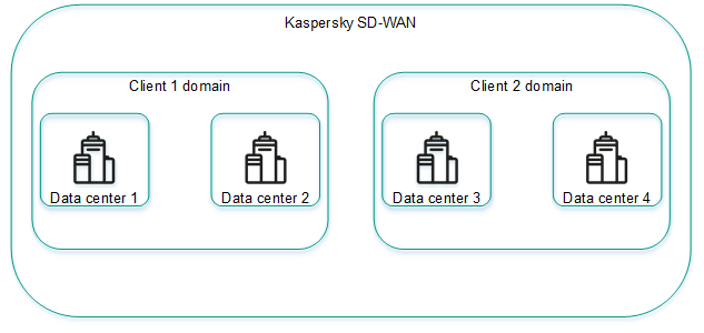
Example of an organization with domains and data centers
Managing domains
The list of domains is displayed in the Infrastructure section, in the Resources pane. Under the domains, the list displays data centers added to the domains.
Creating a domain
To create a domain:
- In the menu, go to the Infrastructure section.
This opens the resource management page. By default, the Network resources tab is selected, which displays the table of controllers.
- In the upper part of the page, click + Domain.
- This opens a window; in that window, in the Name field, enter the name of the domain. The maximum length of the name is 50 characters.
- If necessary, in the Description field, enter a brief description of the domain. The maximum length of the description is 100 characters.
- Click Create.
The domain is created and displayed in the Resources pane.
You can add data centers to a domain when you add data centers.
Page topEditing a domain
To edit a domain:
- In the menu, go to the Infrastructure section.
This opens the resource management page. By default, the Network resources tab is selected, which displays the table of controllers.
- In the Resources pane, click the settings icon
 → Edit next to the domain that you want to edit.
 - This opens a window; in that window, edit the name and/or description of the domain, if necessary.
- Click Save.
The domain is modified and displayed in the Resources pane.
Page topDeleting a domain
Before deleting a domain, you need to delete data centers that have been added to the domain.
Deleted domains cannot be restored.
To delete a domain:
- In the menu, go to the Infrastructure section.
This opens the resource management page. By default, the Network resources tab is selected, which displays the table of controllers.
- In the Resources pane, click the settings icon → Delete next to the domain that you want to delete.
- In the confirmation window, click Delete.
The domain is deleted and is no longer displayed in the Resources pane.
Page topManaging data centers
Lists of data centers are displayed in the Infrastructure in the Resources pane under domains. Before adding data centers, you must create at least one domain.
Adding a data center
To add a data center:
- In the menu, go to the Infrastructure section.
This opens the resource management page. By default, the Network resources tab is selected, which displays the table of controllers.
- In the upper part of the page, click + Data center.
- This opens a window; in that window, in the Name field, enter the name of the data center. The maximum length of the name is 50 characters.
- If necessary, in the Description field, enter a brief description of the data center. The maximum length of the description is 100 characters.
- In the Domain drop-down list, select the created domain to which you want to add the data center. After adding the data center, you can move it to a different domain.
- If you want to deploy virtual network functions and run scripts on CPE devices, in the VNFM URL field, enter the web address of the virtual network function manager to which the orchestrator connects. To verify that the VNFM is available, you can click Test connection.
- If necessary, in the Location field, enter the geographical address of the data center.
- Click Create.
The data center is added and displayed in the Resources pane.
Editing a data center
To edit a data center:
- In the menu, go to the Infrastructure section.
This opens the resource management page. By default, the Network resources tab is selected, which displays the table of controllers.
- In the Resources pane, click the settings icon → Edit next to the data center you want to edit.
- This opens a window; in that window, if necessary, edit the following settings:
- Name of the data center
- Brief description of the data center
- Web address of the Virtual Network Function Manager
- Address of the data center
- Click Save.
The data center is modified and updated in the Resources pane.
Page topMigrating a data center to a different domain
To migrate a data center to a different domain:
- In the menu, go to the Infrastructure section.
This opens the resource management page. By default, the Network resources tab is selected, which displays the table of controllers.
- In the Resources pane, click the settings icon → Migrate next to the data center you want to migrate to a different domain.
- This opens a window; in that window, select the created domain to which you want to migrate your data center.
- Click Migrate.
The data center is migrated to the new domain and displayed under the new domain in the Resources pane.
Page topDeleting a data center
Deleting a data center makes managing controllers, VIMs, and management subnets impossible. You also no longer can specify the Zabbix proxy server for configuring solution component monitoring.
Deleted data centers cannot be restored.
To delete a data center:
- In the menu, go to the Infrastructure section.
This opens the resource management page. By default, the Network resources tab is selected, which displays the table of controllers.
- In the Resources pane, click the settings icon → Delete next to the data center you want to delete.
- In the confirmation window, click Delete.
The data center is deleted and is no longer displayed in the Resources pane.
Page topManaging management subnets
To display the table of management subnets, go to the Infrastructure menu section, click the added data center, and select the IPAM → Subnet tab. Information about management subnets is displayed in the following columns of the table:
- Name is the name of the management subnet.
- Type is the type of the subnet. Only management subnets are presently supported.
- CIDR is the IPv4 prefix of the management subnet.
- Gateway are IPv4 addresses of gateways that the management subnet assigns to virtual network functions.
- IP range are IP address ranges from which the management subnet assigns IP addresses to CPE devices and virtual network functions.
- DNS are IPv4 addresses of the DNS servers that the management subnet assigns to virtual network functions.
- Static routes are source and destination IPv4 addresses of static routes that the management subnet assigns to virtual network functions.
- Usage is the number of IP addresses that the management subnet has assigned to CPE devices and virtual network functions.
The table of CPE devices and virtual network functions to which the management subnet has assigned IP addresses is displayed on the Usage tab. Information about CPE devices and virtual network functions is displayed in the following table columns:
- Name is the name of the management subnet that assigned an IP address to the CPE or virtual network function.
- IP is the IP address assigned to the CPE device or virtual network function.
- Client name is the name of the CPE device or virtual network function.
- Client type is information about whether the control subnet has assigned an IP address to the CPE device or virtual network function:
- VNF
- CPE
- Tenant is the tenant to which the CPE device was added or virtual network function was assigned.
The actions you can perform with the tables are described in the Managing solution component tables instructions.
Creating a management subnet
To create a management subnet:
- In the menu, go to the Infrastructure section.
This opens the resource management page. By default, the Network resources tab is selected, which displays the table of controllers.
- In the Resources pane, select the created domain, then select the added data center in which you want to create the management subnet. After the management subnet is created, it cannot be moved to a different data center.
- Select the IPAM tab.
A table of management subnets is displayed.
- In the upper part of the page, click + Subnet.
- In the Name field, enter the name of the management subnet.
- In the IP version drop-down list, select the version of IP addresses in the management subnet:
- IPv4 Default value.
- IPv6
- In the CIDR field, enter the IPv4 prefix of the management subnet.
- If you want the management subnet to assign a particular gateway to virtual network functions, enter the IPv4 address of the gateway in the Gateway field.
- Specify the IP address range from which the management subnet assigns IP addresses to CPE devices and virtual network functions. To do so, under IP range, click + Addand in the displayed fields, enter the starting and ending values of the IP address range.
The IP address range is specified and displayed in the IP range section. You can specify multiple IP address ranges or delete an IP address range. To delete an IP address range, click the delete icon
 next to it.
 - Specify the DNS server that the management subnet assigns to virtual network functions. To do so, under DNS, click + Add and in the displayed field, enter the IPv4 address of the DNS server.
The DNS server is specified and displayed in the DNS section. You can specify multiple DNS servers or delete a DNS server. To delete a DNS server, click the delete icon
next to it. - Specify the static route that the management subnet assigns to virtual network functions. To do so, under Static routes, click + Add and in the displayed fields, enter the source and destination IPv4 addresses of the static route.
The static route is specified and displayed in the Static routes section. You can specify multiple static routes or delete a static route. To delete a static route, click the delete icon
next to it. - Click Create.
The management subnet is created and displayed in the table.
Page topEditing a management subnet
To edit a management subnet:
- In the menu, go to the Infrastructure section.
This opens the resource management page. By default, the Network resources tab is selected, which displays the table of controllers.
- In the Resources pane, select the created domain, then select the added data center in which you created the management subnet.
- Select the IPAM tab.
A table of management subnets is displayed.
- Click Management → Edit next to the management subnet that you want to edit.
- This opens a window; in that window, edit the following settings, if necessary:
- Name of the management subnet
- IPv4 prefix of the management subnet
- IPv4 addresses of gateways that the management subnet assigns to virtual network functions
- IP address ranges from which the management subnet assigns IP addresses to CPE devices and virtual network functions
- DNS servers that the management subnet assigns to virtual network functions
- Static routes that the management subnet assigns to virtual network functions
- Click Save.
The management subnet is modified and updated in the table.
Page topDeleting a management subnet
Deleted management subnets cannot be restored.
To delete a management subnet:
- In the menu, go to the Infrastructure section.
This opens the resource management page. By default, the Network resources tab is selected, which displays the table of controllers.
- In the Resources pane, select the created domain, then select the added data center in which you created the management subnet.
- Select the IPAM tab.
A table of management subnets is displayed.
- Click Management → Delete next to the management subnet that you want to delete.
- In the confirmation window, click Delete.
The management subnet is deleted and is no longer displayed in the table.
Page topManaging controllers
To display the table of controllers, go to the Infrastructure menu section, click the created data center, and select the Network resources tab. Information about controllers is displayed in the following columns of the table:
- Name is the name of the controller.
- Transport/service strategy is the being used.
- Controller nodes are IP addresses of controller nodes.
- Connection type is the type of connection of CPE devices to the controller:
- Unicast
- Multicast
- Cluster status is the status of the cluster of controller nodes:
- Up means the cluster is operating normally.
- DEGRADED means an error occurred during the operation of the cluster.
- Down means the cluster is not operational.
- Node statuses is the status of controller nodes:
- Connected (primary) means the node is connected to the controller and is the primary node in the cluster.
- Connected (single) means the node is connected to the controller and is the only node in the cluster.
- Connected (secondary) means the node is connected to the controller and is a secondary node in the cluster.
- Disconnected means the node is not connected to the controller.
- Not in cluster means the node is not added to a cluster.
- Unavailable means the node is not available.
- Unknown means the status of the node is unknown.
The actions you can perform with the table are described in the Managing solution component tables instructions.
Editing a controller
To edit a controller:
- In the menu, go to the Infrastructure section.
This opens the resource management page. By default, the Network resources tab is selected, which displays the table of controllers.
- Click Management → Edit next to the controller that you want to edit.
- This opens a window; in that window, in the Name field, enter the name of the controller. Range of values: 1 to 128 characters.
- If necessary, in the Description field, enter a brief description of the controller.
- In the Controller installation on <1>/<3>/<5> servers field, select the number of controller nodes.
- In the Connection type drop-down list, select the type of connection of CPE devices to the controller:
- Unicast
- Multicast
- Configure the controller node:
- In the Address (IP or hostname) field, enter the IP address or hostname of the controller node.
- In the gRPC port field, enter the gRPC port number of the controller node.
- In the JGroups port field, enter the jGroups port number of the controller node.
- If you want to make the controller node the primary node, select the Primary option.
You can configure multiple controller nodes.
- Click Save.
The controller is modified and updated in the table.
Page topReprovisioning a controller
During reprovisioning, controller properties are reset to their default values. This may help resolve errors.
To reprovision the controller:
- In the menu, go to the Infrastructure section.
This opens the resource management page. By default, the Network resources tab is selected, which displays the table of controllers.
- Click Management → Reprovision next to the controller that you want to reprovision.
- In the confirmation window, click Reprovision.
The controller is reprovisioned.
Page topRestoring a controller
You can download a file with controller settings and later use the file to restore the controller if necessary.
To restore a controller:
- In the menu, go to the Infrastructure section.
This opens the resource management page. By default, the Network resources tab is selected, which displays the table of controllers.
- Click Management → Download backup file next to the controller whose settings file you want to download.
A file with controller settings in YAML format is saved to your local device.
- Click Management → Restore next to the controller that you want to restore.
- This opens a window; in that window, specify the path to the downloaded file with controller settings.
- Click Restore.
The controller is restored with settings from the controller settings file.
Page topEnabling or disabling the maintenance mode on a controller
You can enable maintenance mode on the controller when performing maintenance work related to the SD-WAN network to minimize the impact of the controller on parts of the SD-WAN network that are not affected by the maintenance work. In maintenance mode, the controller monitors the status of the SD-WAN network, but does not take any action when the parameters of the SD-WAN network change. For example, in maintenance mode the controller does not rebuild links and paths, does not rewrite MAC addresses of service interfaces, or change transport services.
When you disable maintenance mode, the controller performs actions corresponding to the changes you made to the parameters of the SD-WAN network.
To enable or disable maintenance mode on the controller:
- In the menu, go to the Infrastructure section.
This opens the resource management page. By default, the Network resources tab is selected, which displays the table of controllers.
- Do one of the following:
- If you want to enable maintenance mode on the controller, click Management → Enable maintenance next to it.
- If you want to disable maintenance mode on the controller, click Management → Disable maintenance next to it.
Maintenance mode is enabled or disabled on the controller.
Page topDeleting a controller
Deleted controllers cannot be restored.
To delete a controller:
- In the menu, go to the Infrastructure section.
This opens the resource management page. By default, the Network resources tab is selected, which displays the table of controllers.
- Click Management → Delete next to the controller that you want to delete.
- In the confirmation window, click Delete.
The controller is deleted and is no longer displayed in the table.
Page topManaging controller properties
Properties regulate the operation of the controller. Each property has a change method that determines whether the property value can be changed and when the change takes effect. The following change methods are available:
- Read-only means the property cannot be changed.
- Reload means that when a property is changed, the orchestrator commits the new value to the database of the controller. The new value takes effect after the controller is restarted.
A property value that is in the database, but has not yet taken effect is called a planning value. You can delete a planning value before restarting the controller to keep the current value.
- Runtime means the new value takes effect immediately when the property is modified.
Modifying properties may lead to unstable operation of the controller, so we recommend contacting Kaspersky Technical Support before managing properties.
You can view the table of all controller properties or only changeable controller properties:
- To display the table of all controller properties, navigate to the Infrastructure section, click the added data center, select the Network resources tab, and click Management → Properties next to the controller.
- To display the table of changeable properties of the controller, navigate to the Infrastructure section, click the added data center, select the Network resources tab, click Management → Properties next to the controller and select the Changeable properties tab.
Information about controller properties is displayed in the following columns of the table:
- Change method is the change method of the property.
- Property is the name of the property.
- Current value is the current value of the property.
- Planned value is the planning value of the property. This column is displayed only on the Changeable properties tab.
The actions you can perform with the table are described in the Managing solution component tables instructions.
Description of editable controller properties
Modifying properties may lead to unstable operation of the controller, so we recommend contacting Kaspersky Technical Support before managing properties.
Property |
Description |
|
Buffer size, in bytes, for messages coming in from switches on the controller. |
|
Buffer size, in bytes, for messages going out to switches on the controller. |
|
The starting port number in the range of switch ports. Ports with the next three consecutive numbers are added to the range. For example, if you enter |
|
Whether the TCP_NODELAY parameter is used for management sessions between switches and the controller. Possible values:
|
|
Whether the epoll system is used by the controller when managing switches. Possible values:
|
|
Time in milliseconds after which management sessions between the switches and the controller go idle in absence of read or write operations. The countdown starts anew whenever a read or write operation is performed. |
|
Time in milliseconds after which management sessions between the switches and the controller go idle in absence of read operations. The countdown starts anew whenever a read operation is performed. |
|
Time in milliseconds after which management sessions between the switches and the controller go idle in absence of write operations. The countdown starts anew whenever a write operation is performed. |
|
Netty threads preferentially run on separate CPU cores for separate switches. Possible values:
|
|
Number of Netty threads for handling new switch connections. |
|
Path to the PEM file of the root certificate that was used to sign the OpenFlow certificate. |
|
Path to the PEM file of the encryption certificate for OpenFlow traffic between the controller and switches. |
|
Path to the PEM file with the private key of the OpenFlow certificate. |
|
When the Netty buffer of the management session between switches and the controller contains this number of bytes, the queue is used to write to the session. |
|
When the Netty buffer of the management session between switches and the controller contains this number of bytes, the queue is no longer used to write to the session. This property is used when the number of bytes reaches the |
|
The throughput of the policer on the switches when sending traffic packets through the management session between the switches and the controller. Traffic packets are copied by interception flow rules. |
|
Time, in seconds, after which flow rules automatically created by the controller when processing the first intercepted traffic packet are deleted on the switches to block subsequent packets. The countdown starts anew every time the flow rule is applied. |
|
Bonding of parallel links between two switches. Possible values:
|
|
Whether the equal cost algorithm is used when bonding links. Possible values:
If you specify |
|
Maximum number of links in a bonded link. |
|
Type of the bonded link group. Possible values:
|
|
Whether the controller periodically sends LLDP packets only to enabled ports to detect links between switches. Possible values:
|
|
Whether the switches relay LLDP packets to the controller only from enabled ports when the controller attempts to discover links between the switches. Possible values:
|
|
Interval in milliseconds for the controller sending LLDP packets through the switch links. |
|
Interval in milliseconds for the receiving side of switch links to receive LLDP packets and forward the LLDP packets to the controller. If no LLDP packets arrive through the link within the specified time, the controller considers the link unavailable. |
|
Whether switches send notifications to the controller whenever flow rules that send traffic packets to the controller are deleted. Possible values:
|
|
Interval in milliseconds for checking the connection of switches to the controller. |
|
Time in milliseconds within which disconnected switches must reconnect to the controller. |
|
Number of the last virtual network interface (VNI) in the range of switch interfaces. |
|
Number of the first virtual network interface in the range of switch interfaces. |
|
Whether link Dampening is used. Possible values:
|
|
Maximum time in milliseconds for which access to the link can be restricted. When the specified time elapses, all Dampening counters are reset. |
|
The number by which Penalty is incremented when the link changes state. |
|
The Penalty value at which access to the link is restricted. |
|
Time in milliseconds within which the Penalty must reach the |
|
The IEEE 802.1Q TPID value that is specified as the inner tag for traffic packets with Q-in-Q traffic classification. |
|
The IEEE 802.1Q TPID value that is specified as the outer tag for traffic packets with Q-in-Q traffic classification. |
|
Getting statistics on switches. Statistics contain information about network devices to which the switch is connected, as well as the ports being used. Possible values:
|
|
Value of the 'cookie' field in the message for requesting statistics from the switches. Possible values:
This property must be specified if for |
|
ID of the LLDP packet queue on the switches. |
|
Maximum size of the push notification queue on the switches. If this size is exceeded, the first push notification in the queue is deleted. |
|
Duration in seconds for which IP addresses and ports of switches are blocked after an attempt to connect to the controller with an invalid TLS certificate. |
|
Whether IP addresses and ports of switches are blocked after an attempt to connect to the controller with an invalid TLS certificate. Possible values:
|
|
Time in seconds within which the switches must make the number of attempts (specified in the |
|
The number of attempts of switches to connect to the controller with an invalid TLS certificate, after which the IP addresses and ports of the switches are blocked. |
|
This property is no longer used. |
|
This property is no longer used. |
|
Whether flow rules send traffic packets to the controller. Possible values:
|
|
This property is no longer used. |
|
Interval in milliseconds for checking the latency between the controller and the switches. |
|
Whether latency is checked between the controller and switches. Possible values:
|
|
Number of leading traffic packets on the switches, which is not counted towards statistics. |
|
Number of trailing traffic packets on the switches, which is not counted towards statistics. |
|
Size, in bytes, of chunks of serialized OpenFlow messages that the controller sends to the switches. |
|
Maximum number of blocks of serialized OpenFlow messages in the controller queue. |
|
This property is no longer used. |
|
This property is no longer used. |
|
This property is no longer used. |
|
This property is no longer used. |
|
Maximum number of paths in a segment. |
|
Maximum number of SPF paths for automatic balancing. |
|
Action that switches perform with traffic packets that are not in any of the OpenFlow tables. Possible values:
|
|
Whether Connectivity Fault Management (CFM) is used on links. Possible values:
|
|
Whether controller debug routines are used involving the gRPC protocol. Possible values:
|
|
Establishing links between VTEPs. Possible values:
|
|
Using all links as a last resort when routing traffic, regardless of the link quality. Possible values:
|
|
Link discovery by groups. Possible values:
|
|
Traffic encryption on links. Possible values:
|
|
Interval in minutes for updating the decryption key on links. |
|
Monitoring of errors on links. Possible values:
|
|
Threshold value of the number of errors per second on links. |
|
Interval in seconds for measuring the number of errors on links and link utilization. |
|
Whether Forward Error Correction (FEC) is used on links. Possible values:
|
|
Ratio of original traffic packets to additional packets with redundant code. Enter a value in the |
|
The maximum time, in milliseconds, during which a traffic packet can stay in the queue for FEC to apply. |
|
Monitoring of jitter on links. Possible values:
|
|
Time threshold of jitter on links, in milliseconds. |
|
Monitoring of latency on links. Possible values:
|
|
Latency threshold on links, in milliseconds. |
|
Interval in seconds for comparing the received monitoring figures with the specified thresholds of latency, jitter, and packet loss on links. |
|
Monitoring of latency, jitter, and traffic packet loss on links. Possible values:
You can specify the monitoring protocol using the |
|
Size in bytes of the additional buffer in each LLDP packet for latency, jitter, and packet loss monitoring figures. This property must be specified if for |
|
Protocol for monitoring of latency, jitter, and traffic packet loss on links. Possible values:
|
|
The multiplier that the controller applies to delay, jitter, and packet loss monitoring figures. This property must be specified if for |
|
Monitoring of traffic packet loss on links. Possible values:
|
|
Threshold value of the traffic packet loss percentage on links. |
|
Interval in seconds for automatic detection of the MTU figure on links. |
|
How long the controller waits for a PMTUD LLDP packet, in milliseconds. If the controller does not receive a PMTUD LLDP packet within this time, the controller concludes that a packet of this size cannot be transmitted over the link. |
|
Interval in seconds for monitoring of link thresholds. |
|
Threshold monitoring on links. Possible values:
|
|
Number of successful checks in a row for a link to be unblocked. A check is performed once per second. |
|
Monitoring of link utilization (bandwidth usage). Possible values:
|
|
Threshold value of link utilization as a percentage of the bandwidth of service interfaces. |
|
Concurrent sending of LLDP packets by the controller for link discovery. Possible values:
|
|
Minimum number of streams for concurrent sending of LLDP packets by the controller. This property must be specified if for |
|
Maximum number of streams for concurrent sending of LLDP packets by the controller. This property must be specified if for |
|
Maximum queue size when the controller is sending LLDP packets concurrently. This property must be specified if for |
|
The reserve service interface becomes reserve again if the old service interface becomes operational again. Possible values:
|
|
Accumulation of physical operations on the controller, such as connecting a switch or a port, to perform the operations when the specified time elapses. Possible values:
You can specify the time using the |
|
Time in seconds after which the physical operations accumulated on the controller are carried out. This property must be specified if for |
|
Time in seconds after which the physical operations accumulated on the controller are carried out. The countdown starts anew whenever a physical operation appears. This property can be specified if for |
|
System property. Editing this property may render the controller inoperable. |
|
System property. Editing this property may render the controller inoperable. |
Editing a controller property
Changes you make to the controller properties with the Runtime change method take effect immediately. Changes you make to controller properties with the Reload change method take effect after the controller is restarted.
To change a controller property:
- In the menu, go to the Infrastructure section.
This opens the resource management page. By default, the Network resources tab is selected, which displays the table of controllers.
- Click Management → Properties next to the controller for which you want to change a property.
The controller properties page is displayed. By default, the All properties tab is selected, which displays a table of all controller properties.
- Select the Changeable properties tab.
A table of editable properties of the controller is displayed.
- Click Management → Edit next to the controller property that you want to edit.
- This opens a window; in that window, in the Planned value field, enter the new value of the controller property.
- Click Save.
The new value of a property with the Runtime method is displayed in the Current value column. The new value of a property with the Reload method is displayed in the Planned value column.
Deleting planning values of controller properties
You can delete a planning value to undo a controller property change. This action is applicable only to properties that have the Reload method.
Deleted planning values of controller properties cannot be restored.
To delete planning values of controller properties:
- In the menu, go to the Infrastructure section.
This opens the resource management page. By default, the Network resources tab is selected, which displays the table of controllers.
- Click Management → Properties next to the controller for which you want to delete planning values of properties.
The controller properties page is displayed. By default, the All properties tab is selected, which displays a table of all controller properties.
- Select the Changeable properties tab.
A table of editable properties of the controller is displayed.
- Delete the planning values of controller properties in one of the following ways:
- If you want to delete the planning value of an individual property of the controller, click Management → Delete planned value next to that property.
- If you want to delete planning values of all controller properties, in the upper part of the table, click the settings icon → Delete all planned values.
- In the confirmation window, click Delete.
The planning values of controller properties are deleted.
Page topResetting controller properties to default values
To reset controller properties to default values:
- In the menu, go to the Infrastructure section.
This opens the resource management page. By default, the Network resources tab is selected, which displays the table of controllers.
- Click Management → Properties next to the controller whose properties you want to reset to default values.
The controller properties page is displayed. By default, the All properties tab is selected, which displays a table of all controller properties.
- Select the Changeable properties tab.
A table of editable properties of the controller is displayed.
- Reset the controller properties in one of the following ways:
- If you want to reset an individual property of the controller to its default value, click Management → Reset property next to that property.
- If you want to reset all controller properties to their default values, click the settings icon in the upper part of the table → Reset all properties.
- In the confirmation window, click Reset.
The controller properties are reset to their default values.
Page topViewing information about controller nodes
To view information about controller nodes:
- In the menu, go to the Infrastructure section.
This opens the resource management page. By default, the Network resources tab is selected, which displays the table of controllers.
- Click Management → Configuration menu next to the controller for which you want to view information about nodes.
This opens the controller configuration menu. By default, you are taken to the Controller nodes section, which displays a table of controller nodes. Information about controller nodes is displayed in the following columns of the table:
- Address is the IP address of the controller node.
- Status is the status of the controller node:
- Connected (primary) means the node is connected to the controller and is the primary node in the cluster.
- Connected (single) means the node is connected to the controller and is the only node in the cluster.
- Connected (secondary) means the node is connected to the controller and is a secondary node in the cluster.
- Disconnected means the node is not connected to the controller.
- Not in cluster means the node is not added to a cluster.
- Unavailable means the node is not available.
- Unknown means the status of the node is unknown.
- gRPC port is the number of the gRPC port of the controller node.
- JGroups port is the JGroups port number of the controller node.
- Version is the version of the controller node software.
The actions that you can perform with the table are described in the Managing solution component tables instructions.
- If you want to view statistics for a controller node, click Management →Statistics next to the node.
- If you want to view the properties of a controller node, click Management → Node properties next to the node.
Managing a VIM
You can deploy a VIM in one of your data centers or on a uCPE device. Deploying the VIM in a data center implies centralized management of the virtual network function lifecycle. Deploying the VIM on a uCPE device lets you deliver virtual network functions to remote data centers and manage them locally.
To display the table of VIMs, go to the Infrastructure menu section, click the created data center, and select the IPAM → Compute resources tab. Information about VIMs is displayed in the following columns of the table:
- Name is the name of the VIM.
- Type is the type of the VIM. Kaspersky SD-WAN uses the OpenStack cloud platform as the VIM.
- Function is the data center or uCPE device on which the VIM is deployed.
- VIM IP is the IP address of the VIM.
- Status is the connection status of the VIM to the OpenStack cloud platform:
- Connected
- Disconnected
- SDN cluster is the SDN cluster to which OpenStack is connected.
- Behind NAT lets you specify whether the VIM is behind NAT (Network Address Translation):
- Yes
- No
The actions you can perform with the table are described in the Managing solution component tables instructions.
Configuring a VIM deployed in a data center
To configure a VIM deployed in a data center:
- In the menu, go to the Infrastructure section.
This opens the resource management page. By default, the Network resources tab is selected, which displays the table of SD-WAN Controllers.
- In the Resources pane, select the created domain, then select the added data center in which you deployed the VIM.
- Select the Compute resources tab.
A table of VIMs is displayed.
- In the upper part of the page, click + VIM.
- This opens a window; in that window, in the Name field, enter the name of the VIM.
- In the IP field, enter the IP address or domain name for connecting the orchestrator to the VIM.
- In the Port field, enter the port number for connecting the orchestrator to the VIM identification service. Default value:
5000. - In the Protocol drop-down list, select the protocol for connecting the orchestrator to the VIM:
- http Default value.
- https
- In the Login and Password fields, enter the user name and password of an account with administrator privileges to authenticate the orchestrator in the OpenStack cloud platform. If authentication is successful, the orchestrator gains access to management of virtual infrastructure that is available to the administrator.
- Specify advanced orchestrator authentication settings in the OpenStack cloud platform:
- In the Administrator project field, enter the name of the administrator project for orchestrator authentication in this administrator project.
- In the Domain field, enter the OpenStack domain name for orchestrator authentication in this OpenStack domain.
- In the Behind NAT drop-down list, select whether the VIM is behind NAT:
- Enabled to indicate that the VIM is behind NAT and network address translation happens when the VIM interacts with the SD-WAN instance.
- Disabled to indicate that the VIM is not behind NAT. Default value.
- Specify the overcommitment ratios for physical resources:
- In the CPU overcommitment field, enter the CPU core overcommitment ratio. Default value:
1. - In the RAM overcommitment field, enter the RAM overcommitment ratio. Default value:
1. - In the Disk overcommitment field, enter the disk space overcommitment ratio. Default value:
1.
Overcommitment ratios let you provision virtual machines with more virtual resources than physically present. This is possible because virtual machines do not simultaneously use all available physical resources to the maximum. For example, if you specify a disk space overcommitment factor of
3, the available virtual disk space can be three times as large as the disk space physically available on the host.When configuring overcommitment, you must consider how the capabilities of your hardware relate to the requirements of the virtual machines. If you specify a high overcommitment ratio for physical resources and virtual machines happen to use them up, this may lead to the network lagging and/or parts of network becoming completely unavailable.
- In the CPU overcommitment field, enter the CPU core overcommitment ratio. Default value:
- In the Parallelism field, enter the maximum number of simultaneous operations between the orchestrator and the VIM. Default value:
1. This setting lets you reduce the overall processing time for operations, but creates an additional load on the virtual infrastructure.We recommend not changing the default value unless the overall operation processing speed is critical for you.
- In the SDN cluster drop-down list, select the SDN cluster to which OpenStack is connected. If OpenStack is not connected to an SDN cluster, select None.
- In the Maximum number of VLANs field, enter the maximum number of VLANs that the VIM may use. This setting lets the orchestrator keep track of the number of segments available for use. Range of values: 0 to 4,094.
- If the VIM supports SR-IOV, enter the physnet name in the SR-IOV physical network field. The orchestrator uses the SR-IOV physical network name to connect virtual machines with the SR-IOV interface type.
- If you are using a network with the VLAN segmentation type for management, in the VLAN physical network field, enter the VLAN tag.
- If you selected an SDN cluster in the SDN cluster drop-down list, configure the connection to that cluster:
- If you want to map the logical networks of the SD-WAN instance to a physical network, enter the physnet name in the OpenStack physical network field.
- In the Interface group drop-down list, select the port group through which all OpenStack nodes are connected to the SDN cluster.
- In the Control group drop-down list, select the port group through which the OpenStack control nodes are connected to the SDN cluster.
- If necessary, in the Compute group drop-down list, select the port group through which OpenStack compute nodes are connected to the SDN cluster.
- If in the SDN cluster drop-down list, you selected None, configure the network:
- If you want to map the flat networks of the SD-WAN instance to a physical network, enter the physnet name in the Flat physical network field.
- If you want to map the VXLAN of the SD-WAN instance to a physical network, enter the physnet name in the VXLAN physical network field.
- In the Control network segmentation drop-down list, select the type of segmentation for isolating and securing traffic in the SD-WAN structure:
- VLAN
- VXLAN
- In the Control segment ID field, enter the segment ID of the management network. The range of values depends on the value selected in the Control network segmentation drop-down list:
- If you selected VLAN, the range of values is 0 to 4,095.
- If you selected VXLAN, the range of values is 0 to 16,000,000.
- In the Port security drop-down list, select whether you want to enable the Port security function:
- Enabled
- Disabled
- In the Permit CIDR field, enter the IPv4 prefox of the allowed subnet for the management network.
- Click Create.
The VIM is created and displayed in the table on the Compute resources tab.
Page topConfiguring a VIM deployed on a uCPE device
To configure a VIM deployed on a uCPE device, you must specify the settings of the VIM in a uCPE template. VIM settings specified in a uCPE template are automatically applied to all CPE devices that are using this uCPE template.
To configure a VIM deployed on a uCPE device:
- In the menu, go to the SD-WAN → CPE templates section.
A table of CPE templates is displayed.
- Click the uCPE template in which you want to configure a VIM.
The settings area is displayed in the lower part of the page. You can expand the settings area to fill the entire page by clicking the expand icon
 . By default, the Information tab is selected, which displays general information about the CPE template.
 - Select the VIM tab.
The VIM settings are displayed.
- In the Port field, enter the port number for connecting the orchestrator to the VIM identification service. Default value:
5000. - In the Protocol drop-down list, select the protocol for connecting the orchestrator to the VIM:
- http Default value.
- https
- In the Login and Password fields, enter the user name and password of an account with administrator privileges to authenticate the orchestrator in the OpenStack cloud platform. If authentication is successful, the orchestrator gains access to managing the virtual infrastructure that is available to the administrator.
- Specify advanced orchestrator authentication settings in the OpenStack cloud platform:
- In the Administrator project field, enter the name of the administrator project for orchestrator authentication in this project.
- In the Domain field, enter the OpenStack domain name for orchestrator authentication in this domain.
- If you are using a network with the VLAN segmentation type for management, in the VLAN physical network field, enter the VLAN tag.
- In the Behind NAT drop-down list, select whether the VIM is behind NAT:
- Enabled to indicate that the VIM is behind NAT and network address translation happens when it interacts with the SD-WAN instance.
- Disabled to indicate that the VIM is not behind NAT. Default value.
- Specify the overcommitment ratios for physical resources:
- In the CPU overcommitment field, enter the CPU core overcommitment ratio. Default value:
1. - In the RAM overcommitment field, enter the RAM overcommitment ratio. Default value:
1. - In the Disk overcommitment field, enter the disk space overcommitment ratio. Default value:
1.
Overcommitment ratios let you provision virtual machines with more virtual resources than physically present. This is possible because, as a rule, virtual machines do not simultaneously use all available physical resources to the maximum. For example, if you specify a disk space overcommitment factor of
3, the available virtual disk space can be three times as large as the disk space physically available on the host.When configuring overcommitment, you must consider how the capabilities of your hardware relate to the requirements of the virtual machines. If you specify a high overcommitment ratio for physical resources and virtual machines happen to use them up, this may lead to the network lagging and/or parts of network becoming completely unavailable.
- In the CPU overcommitment field, enter the CPU core overcommitment ratio. Default value:
- In the Maximum number of VLANs field, enter the maximum number of VLANs that the VIM may use. This setting lets the orchestrator keep track of the number of segments available for use. Range of values: 0 to 4,094.
- In the upper part of the settings area, click Save to save CPE template settings.
Editing a VIM deployed in a data center
To edit a VIM deployed in a data center:
- In the menu, go to the Infrastructure section.
This opens the resource management page. By default, the Network resources tab is selected, which displays the table of controllers.
- In the Resources pane, select the created domain, then select the added data center in which you deployed the VIM.
- Select the Compute resources tab.
A table of VIMs is displayed.
- Click Management → Edit next to the VIM that you want to edit.
- This opens a window; in that window, edit the VIM settings, if necessary. For a description of the settings, refer to the instructions for configuring a VIM deployed in a data center.
- Click Save.
The VIM is modified and updated in the table.
Page topViewing computing resources being used by a VIM
You can view the utilization of the following computing resources by the VIM:
- CPU
- RAM
- Disk space
- Network segments
To view the computing resources used by the VIM:
- In the menu, go to the Infrastructure section.
This opens the resource management page. By default, the Network resources tab is selected, which displays the table of controllers.
- In the Resources pane, select the created domain, then select the added data center in which you deployed the VIM.
- Select the Compute resources tab.
A table of VIMs is displayed.
- Click Management → Show usage next to the VIM.
This opens a window with information about the computing resources used by the VIM.
Page topDeleting a VIM
Deleted VIMs cannot be restored.
To delete a VIM:
- In the menu, go to the Infrastructure section.
This opens the resource management page. By default, the Network resources tab is selected, which displays the table of controllers.
- In the Resources pane, select the created domain, then select the added data center in which you deployed the VIM.
- Select the Compute resources tab.
A table of VIMs is displayed.
- Click Management → Delete next to the VIM that you want to delete.
- In the confirmation window, click Delete.
The VIM is deleted and is no longer displayed in the table.
Page top