Contents
Managing network services
The list of network services is displayed on the self-service portal in the Infrastructure section, on the Network services pane. Before managing network services, you must log in to the tenant's self-service portal.
Creating a network service
To create a network service:
- In the menu, go to the Catalog section.
The network service management page is displayed.
- In the upper part of the Network services pane, click + Network service.
The graphical design tool for building the topology is displayed.
- Add network service components to the topology:
- Drag network server components from the Catalog pane into the graphical design tool. The pane displays the following network service components:
- Network service templates — when you add a network service template to a topology, the topology is constructed in accordance with the network service template. You can add multiple network service templates to the topology.
- Shared network services — you must add a shared network service to the topology of network services that you want to connect to the shared network service. You can specify a brief description of the shared network service.
- Virtual and physical network functions. The actions that you can perform on virtual and physical network functions are described in the Managing virtual network functions and Managing physical network functions sections.
- Drag and drop links from the Links tab into the graphical design tool. The following links are displayed on this tab:
- P2P is the Point-to-Point transport service (P2P service). You can configure a P2P service.
- P2M is the Point-to-Multipoint transport service (P2M service). You can configure a P2M service.
- M2M is a Multipoint-to-Multipoint transport service (M2M service). You can configure an M2M service.
The remaining links are relevant to network communication at the VIM level and are established between VNFs hosted by the OpenStack cloud platform:
- OS shared is the shared network through which the shared network service connects to network services. You can configure a shared network.
- OS vRouter is the virtual L3 router. You can configure a virtual router.
- OS VLAN is the VLAN for transmitting tagged L2 traffic of the 802.1Q standard You can configure a VLAN.
- OS VXLAN is a VXLAN for tunneling. You can configure a VXLAN.
- OS flat is the flat network for transmitting untagged L2 traffic You can configure a flat network.
- Select the UNI tab and drag CPE device UNIs to the graphical design tool. If you are using a network service template, you must replace the abstract UNIs in the topology with real UNIs. Abstract UNIs can be designated by two components, UNI and WAN. The WAN component refers to UNIs that connect to the WAN.
You can configure a UNI.
- Drag network server components from the Catalog pane into the graphical design tool. The pane displays the following network service components:
- Connect the network service components added to the topology to each other:
- Click the link to which you want to connect a network service component.
- Click Add leaf to connect a network service component with the leaf role to the link. If you clicked a P2M service, you can click Add root to connect a network service component with the root role to the link.
- Click the network service component that you want to connect to the link. If you clicked a network function or shared network service, select the port to connect the link to in the displayed window.
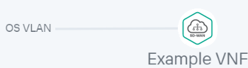
The network service component is connected to the link, and a line is displayed between them in the topology. For example, the figure below shows the VLAN to which a virtual network function is connected.
- If you want to assign backup UNIs:
A backup UNI can be assigned only for UNIs which are connected to at least one link.
- Click the UNI for which you want to assign a backup UNI.
- Click Reserve.
- Click the UNI that you want to use as the backup.
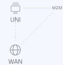
The UNI is designated as the backup UNI, and a dotted line is displayed between the UNI, the backup UNI, and the link to which the UNI is connected. For example, in the figure below, the WAN is the backup interface for the UNI.
- If you want to remove a network service component from the topology, click the component, then click Delete.
The network service component is removed from the topology and is no longer displayed in the graphical design tool.
- If you want to horizontally align the topology, click Arrange.
- If you do not want to hide the descriptions of the added network service components in the topology, clear the Description check box. This check box is selected by default.
- In the Name field, enter the name of the network service.
- Finish creating the network service in one of the following ways:
- To save the network service, click Save.
- To save and deploy the network service, click Deploy.
The network service is created and displayed in Network services pane. If you clicked Deploy, the deployment of the network service begins, which may take several minutes. You can interrupt the deployment by clicking Abort deploy.
Editing a network service
To edit a network service:
- In the menu, go to the Catalog section.
The network service management page is displayed.
- In the Network services pane, select the network service that you want to edit.
The graphical design tool for building the topology is displayed.
- In the upper part of the graphical design tool, click Edit.
- If necessary, edit the settings of the network service. For a description of the settings, see the instructions for creating a network service.
- Finish editing the network service in one of the following ways:
- If you are editing a network service that is not deployed, do one of the following:
- To save the network service, click Save.
- To save and deploy the network service, click Deploy.
- If you are editing a deployed network service, click Deploy changes to deploy the modified network service.
- If you are editing a network service that is not deployed, do one of the following:
The network service is modified and updated in Network services pane. If you clicked Deploy or Deploy changes, deployment begins, which may take several minutes. You can interrupt the deployment by clicking Abort deploy.
Page topDeploying a network service
If a virtual network function deployed on a uCPE device is added to the network service topology and there is connectivity between the orchestrator and the uCPE device, this network service is deployed when connectivity is restored.
To deploy a network service:
- In the menu, go to the Catalog section.
The network service management page is displayed.
- In the Network services pane, select the network service that you want to deploy.
The graphical design tool for building the topology is displayed.
- In the upper part of the graphical design tool, click Edit.
- Click Deploy.
This starts the deployment of the network service, which may take several minutes. You can interrupt the deployment by clicking Abort deploy.
Checking the consistency of a network service
The consistency check allows verifying that the components are added to the network service topology actually exist.
To check the consistency of a network service:
- In the menu, go to the Catalog section.
The network service management page is displayed.
- In the Network services pane, click the settings icon
 → Check consistency next to the network service whose consistency you want to check.
 - In the confirmation window, click Confirm.
This begins the consistency check of the network service.
Page topRedeploying a network service
Redeploying a network service may result in short-term interruptions or temporary inoperability. When planning redeployment activities, we recommend taking into account your organization's circumstances to minimize the disruptions.
To redeploy a network service:
- In the menu, go to the Catalog section.
The network service management page is displayed.
- In the Network services pane, click the settings icon → Redeploy next to the network service that you want to redeploy.
- In the confirmation window, click Confirm.
This starts the redeployment of the network service, which may take several minutes. You can interrupt the deployment by clicking Abort deploy.
Page topDisabling or enabling auto-healing for a network service
The Zabbix server monitors network service components and sends a REST API request to the orchestrator whenever a problem is detected. If the auto-healing functionality is enabled for the network service, the orchestrator initiates auto-healing for components with problems. By default, this functionality is enabled.
To disable or enable auto-healing for a network service:
- In the menu, go to the Catalog section.
The network service management page is displayed.
- In the Network services pane, click the settings icon → Disable Auto-Healing or Enable Auto-Healing next to the network service for which you want to disable or enable auto-healing.
Auto-healing is disabled or enabled for the network service.
You can perform auto-healing of virtual network functions or their VDUs even if auto-healing is disabled for the network service.
Page topViewing the network service log
To view the log of a network service:
- In the menu, go to the Catalog section.
The network service management page is displayed.
- In the Network services pane, click the settings icon → Open log next to the network service whose log you want to view.
The page with the network service log is displayed.
Page topDeleting a network service
Deleted network services cannot be restored.
To delete a network service:
- In the menu, go to the Catalog section.
The network service management page is displayed.
- In the Network services pane, click the settings icon → Delete next to the network service that you want to delete.
- In the confirmation window, click Delete.
The network service is deleted and is no longer displayed in the Network services pane.
Page top