Contents
- Managing network services and virtualization of network functions
- Managing network service templates
- Managing network services
- Scenario: Deploying a virtual network function
- Scenario: Deploying a physical network function
- Managing VNF and PNF packages
- Specifying a brief description of a shared network service
- Managing virtual network functions
- Selecting the flavour of a virtual network function
- Configuring external connection points of a virtual network function
- Basic settings of a virtual network function
- Hosting the virtual network function in a data center and on a uCPE device
- Stopping or starting a virtual network function or a VDU that is part of it
- Pausing or unpausing a virtual network function or a VDU that is part of it
- Suspending or unsuspending a virtual network function or a VDU that is part of it
- Soft rebooting a virtual network function or a VDU that is part of it
- Hard rebooting of a virtual network function or a VDU that is part of it
- Redeploying a virtual network function or a VDU that is part of it
- Auto-healing a virtual network function or a VDU that is part of it
- Managing VDU snapshots
- Managing physical network functions
- Configuring a P2P service
- Configuring a P2M service
- Configuring an M2M service
- Configuring a shared network (OS 2 SHARED)
- Configuring a virtual router (OS vRouter)
- Configuring a VLAN
- Configuring a VXLAN
- Configuring a flat network
- Configuring a UNI
Managing network services and virtualization of network functions
Network services
Network services relay traffic over the network and apply network functions to it, such as WAN optimization, shaping, and traffic protection. Each network service has a topology that you build using a graphical design tool. You can add components to the topology and connect them to each other.
You can build a topology in a network service template and then assign that network service template to a tenant. Components added to the template topology are automatically assigned to the tenant together with the network service template. A tenant can create and deploy network services, if necessary, using assigned network service templates, and edit network services that are already deployed.
You can use network services to deploy SD-WAN instances. The network service for deploying SD-WAN instances is called the SD-WAN network service (SD-WAN service).
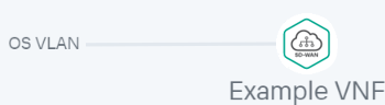
An example of a network service topology is shown in the figure below.

Network service topology
Network function virtualization
Network function virtualization (NFV) lets you use virtualized storage, compute resources, and networks to provide network functions and combine these into network services.
You can deploy virtual network functions (VNF) and physical network functions (PNF) in network services. The difference between virtual and physical network functions is that the orchestrator does not manage the lifecycle of physical network functions. Third-party network functions are supported.
Kaspersky SD-WAN complies with the architecture specified in the ETSI NFV MANO specification (NFV Management and Network Orchestration), which defines the following main functional components:
- .
- .
- .
- The Zabbix monitoring system monitors the status of virtual and physical network functions and notifies the orchestrator when a network function needs to be restored or scaled.
- The NFV infrastructure consists of physical resources such as hardware storage, servers, and network devices.
- .
The figure below shows the relations between the solution components and the NFV infrastructure. Components of external solutions are marked in white, Kaspersky SD-WAN components are marked in green, and the red lines are connections between components.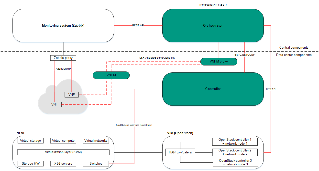
NFV infrastructure
Managing network service templates
A list of network service templates is displayed on the administrator portal in the Infrastructure section, in the Catalog pane on the Templates tab.
Creating a network service template
To create a network service template:
- In the menu, go to the Catalog section.
The network service management page is displayed.
- In the upper part of the page, click + Template.
The graphical design tool for building the topology is displayed.
- Add network service components to the topology:
- Drag network server components from the Catalog pane into the graphical design tool. The pane displays the following network service components:
- Network service templates — when you add a network service template to a topology, the topology is constructed in accordance with the network service template. You can add multiple network service templates to the topology.
- Shared network services — you must add a shared network service to the topology of network services that you want to connect to the shared network service. You can specify a brief description of the shared network service.
- Virtual and physical network functions. The actions that you can perform on virtual and physical network functions are described in the Managing virtual network functions and Managing physical network functions sections.
- Drag and drop links from the Links tab into the graphical design tool. The following links are displayed on this tab:
- P2P is the Point-to-Point transport service (P2P service). You can configure a P2P service.
- P2M is the Point-to-Multipoint transport service (P2M service). You can configure a P2M service.
- M2M is a Multipoint-to-Multipoint transport service (M2M service). You can configure an M2M service.
The remaining links are relevant to network communication at the VIM level and are established between VNFs hosted by the OpenStack cloud platform:
- OS shared is the shared network through which the shared network service connects to network services. You can configure a shared network.
- OS vRouter is the virtual L3 router. You can configure a virtual router.
- OS VLAN is the VLAN for transmitting tagged L2 traffic of the 802.1Q standard You can configure a VLAN.
- OS VXLAN is a VXLAN for tunneling. You can configure a VXLAN.
- OS flat is the flat network for transmitting untagged L2 traffic You can configure a flat network.
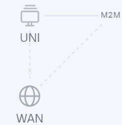
- Select the UNI tab and drag CPE device UNIs to the graphical design tool. The tab displays two components, UNI and WAN. Both components designate abstract UNIs that the tenant must replace with real UNIs when creating or editing a network service. The WAN component refers to UNIs that connect to the WAN.
You can configure a UNI in the topology.
The components are added to the topology and displayed in the graphical design tool.
- Drag network server components from the Catalog pane into the graphical design tool. The pane displays the following network service components:
- Connect the network service components added to the topology to each other:
- Click the link to which you want to connect a network service component.
- Click Add leaf to connect a network service component with the leaf role to the link. If you clicked a P2M service, you can click Add root to connect a network service component with the root role to the link.
- Click the network service component that you want to connect to the link. If you clicked a network function or shared network service, select the port to connect the link to in the displayed window.
The network service component is connected to the link, and a line is displayed between them in the topology. For example, the figure below shows the VLAN to which a virtual network function is connected.
- If you want to assign backup UNIs:
A backup UNI can be assigned only for UNIs which are connected to at least one link.
- Click the UNI for which you want to assign a backup UNI.
- Click Reserve.
- Click the UNI that you want to use as the backup.
The UNI is designated as the backup UNI, and a dotted line is displayed between the UNI, the backup UNI, and the link to which the UNI is connected. For example, in the figure below, the WAN is the backup interface for the UNI.
- If you want to remove a network service component from the topology, click the component, then click Delete.
The network service component is removed from the topology and is no longer displayed in the graphical design tool.
- If you want to horizontally align the topology, click Arrange.
- If you do not want to hide the descriptions of the added network service components in the topology, clear the Description check box. This check box is selected by default.
- In the Name field, enter the name of the network service.
- In the upper part of the graphical design tool, click Save.
The network service template is created and displayed in the Catalog pane, on the Templates tab.
Page topEditing a network service template
When you edit a network service template, the changes are not applied to network services that have already been created and deployed using the network service template.
To edit a network service template:
- In the menu, go to the Catalog section.
The network service management page is displayed.
- In the Catalog pane, select the Templates tab.
A list of network service templates is displayed.
- Click the network service template that you want to edit.
The graphical design tool for building the topology is displayed.
- Edit the settings of the network service template. For a description of the settings, see the instructions for creating a network service template.
- In the upper part of the graphical design tool, click Save.
The network service template is modified and updated in the Templates tab.
Page topDeleting a network service template
Deleted network service templates cannot be restored.
To delete a network service template:
- In the menu, go to the Catalog section.
The network service management page is displayed.
- In the Catalog pane, select the Templates tab.
A list of network service templates is displayed.
- Click the delete icon
 next to the network service template that you want to delete.
 - In the confirmation window, click Delete.
The network service template is deleted and is no longer displayed in the Templates tab.
Page topManaging network services
The list of network services is displayed on the self-service portal in the Infrastructure section, on the Network services pane. Before managing network services, you must log in to the tenant's self-service portal.
Creating a network service
To create a network service:
- In the menu, go to the Catalog section.
The network service management page is displayed.
- In the upper part of the Network services pane, click + Network service.
The graphical design tool for building the topology is displayed.
- Add network service components to the topology:
- Drag network server components from the Catalog pane into the graphical design tool. The pane displays the following network service components:
- Network service templates — when you add a network service template to a topology, the topology is constructed in accordance with the network service template. You can add multiple network service templates to the topology.
- Shared network services — you must add a shared network service to the topology of network services that you want to connect to the shared network service. You can specify a brief description of the shared network service.
- Virtual and physical network functions. The actions that you can perform on virtual and physical network functions are described in the Managing virtual network functions and Managing physical network functions sections.
- Drag and drop links from the Links tab into the graphical design tool. The following links are displayed on this tab:
- P2P is the Point-to-Point transport service (P2P service). You can configure a P2P service.
- P2M is the Point-to-Multipoint transport service (P2M service). You can configure a P2M service.
- M2M is a Multipoint-to-Multipoint transport service (M2M service). You can configure an M2M service.
The remaining links are relevant to network communication at the VIM level and are established between VNFs hosted by the OpenStack cloud platform:
- OS shared is the shared network through which the shared network service connects to network services. You can configure a shared network.
- OS vRouter is the virtual L3 router. You can configure a virtual router.
- OS VLAN is the VLAN for transmitting tagged L2 traffic of the 802.1Q standard You can configure a VLAN.
- OS VXLAN is a VXLAN for tunneling. You can configure a VXLAN.
- OS flat is the flat network for transmitting untagged L2 traffic You can configure a flat network.
- Select the UNI tab and drag CPE device UNIs to the graphical design tool. If you are using a network service template, you must replace the abstract UNIs in the topology with real UNIs. Abstract UNIs can be designated by two components, UNI and WAN. The WAN component refers to UNIs that connect to the WAN.
You can configure a UNI.
- Drag network server components from the Catalog pane into the graphical design tool. The pane displays the following network service components:
- Connect the network service components added to the topology to each other:
- Click the link to which you want to connect a network service component.
- Click Add leaf to connect a network service component with the leaf role to the link. If you clicked a P2M service, you can click Add root to connect a network service component with the root role to the link.
- Click the network service component that you want to connect to the link. If you clicked a network function or shared network service, select the port to connect the link to in the displayed window.
The network service component is connected to the link, and a line is displayed between them in the topology. For example, the figure below shows the VLAN to which a virtual network function is connected.
- If you want to assign backup UNIs:
A backup UNI can be assigned only for UNIs which are connected to at least one link.
- Click the UNI for which you want to assign a backup UNI.
- Click Reserve.
- Click the UNI that you want to use as the backup.
The UNI is designated as the backup UNI, and a dotted line is displayed between the UNI, the backup UNI, and the link to which the UNI is connected. For example, in the figure below, the WAN is the backup interface for the UNI.
- If you want to remove a network service component from the topology, click the component, then click Delete.
The network service component is removed from the topology and is no longer displayed in the graphical design tool.
- If you want to horizontally align the topology, click Arrange.
- If you do not want to hide the descriptions of the added network service components in the topology, clear the Description check box. This check box is selected by default.
- In the Name field, enter the name of the network service.
- Finish creating the network service in one of the following ways:
- To save the network service, click Save.
- To save and deploy the network service, click Deploy.
The network service is created and displayed in Network services pane. If you clicked Deploy, the deployment of the network service begins, which may take several minutes. You can interrupt the deployment by clicking Abort deploy.
Editing a network service
To edit a network service:
- In the menu, go to the Catalog section.
The network service management page is displayed.
- In the Network services pane, select the network service that you want to edit.
The graphical design tool for building the topology is displayed.
- In the upper part of the graphical design tool, click Edit.
- If necessary, edit the settings of the network service. For a description of the settings, see the instructions for creating a network service.
- Finish editing the network service in one of the following ways:
- If you are editing a network service that is not deployed, do one of the following:
- To save the network service, click Save.
- To save and deploy the network service, click Deploy.
- If you are editing a deployed network service, click Deploy changes to deploy the modified network service.
- If you are editing a network service that is not deployed, do one of the following:
The network service is modified and updated in Network services pane. If you clicked Deploy or Deploy changes, deployment begins, which may take several minutes. You can interrupt the deployment by clicking Abort deploy.
Page topDeploying a network service
If a virtual network function deployed on a uCPE device is added to the network service topology and there is connectivity between the orchestrator and the uCPE device, this network service is deployed when connectivity is restored.
To deploy a network service:
- In the menu, go to the Catalog section.
The network service management page is displayed.
- In the Network services pane, select the network service that you want to deploy.
The graphical design tool for building the topology is displayed.
- In the upper part of the graphical design tool, click Edit.
- Click Deploy.
This starts the deployment of the network service, which may take several minutes. You can interrupt the deployment by clicking Abort deploy.
Checking the consistency of a network service
The consistency check allows verifying that the components are added to the network service topology actually exist.
To check the consistency of a network service:
- In the menu, go to the Catalog section.
The network service management page is displayed.
- In the Network services pane, click the settings icon
 → Check consistency next to the network service whose consistency you want to check.
 - In the confirmation window, click Confirm.
This begins the consistency check of the network service.
Page topRedeploying a network service
Redeploying a network service may result in short-term interruptions or temporary inoperability. When planning redeployment activities, we recommend taking into account your organization's circumstances to minimize the disruptions.
To redeploy a network service:
- In the menu, go to the Catalog section.
The network service management page is displayed.
- In the Network services pane, click the settings icon → Redeploy next to the network service that you want to redeploy.
- In the confirmation window, click Confirm.
This starts the redeployment of the network service, which may take several minutes. You can interrupt the deployment by clicking Abort deploy.
Page topDisabling or enabling auto-healing for a network service
The Zabbix server monitors network service components and sends a REST API request to the orchestrator whenever a problem is detected. If the auto-healing functionality is enabled for the network service, the orchestrator initiates auto-healing for components with problems. By default, this functionality is enabled.
To disable or enable auto-healing for a network service:
- In the menu, go to the Catalog section.
The network service management page is displayed.
- In the Network services pane, click the settings icon → Disable Auto-Healing or Enable Auto-Healing next to the network service for which you want to disable or enable auto-healing.
Auto-healing is disabled or enabled for the network service.
You can perform auto-healing of virtual network functions or their VDUs even if auto-healing is disabled for the network service.
Page topViewing the network service log
To view the log of a network service:
- In the menu, go to the Catalog section.
The network service management page is displayed.
- In the Network services pane, click the settings icon → Open log next to the network service whose log you want to view.
The page with the network service log is displayed.
Page topDeleting a network service
Deleted network services cannot be restored.
To delete a network service:
- In the menu, go to the Catalog section.
The network service management page is displayed.
- In the Network services pane, click the settings icon → Delete next to the network service that you want to delete.
- In the confirmation window, click Delete.
The network service is deleted and is no longer displayed in the Network services pane.
Page topScenario: Deploying a virtual network function
You can deploy a virtual network function for a tenant in a network service. The lifecycle of virtual network functions is managed by an orchestrator. To deploy virtual network functions, you need the OpenStack cloud platform.
For example, you can deploy a virtual network function at the central office of your organization to protect user traffic that is transmitted between CPE devices.
Virtual network function deployment involves the following steps:
- Preparing a VNF package
Prepare the VNF package that you want to deploy, and then upload the VNF package to the orchestrator web interface. If necessary, you can enable protection of VNF and PNF packages against substitution before uploading the VNF package to the orchestrator web interface.
- Ensuring network connectivity between the orchestrator and the OpenStack cloud platform
Ensure network connectivity between the virtual machine or physical server where the orchestrator is deployed and the OpenStack cloud platform.
- Assigning the virtual network function to a tenant
Use one of the following methods to assign the virtual network function to the tenant for which you want to deploy it:
- If you want to deploy a virtual network function using a network service template:
- Add the virtual network function to the topology when creating or editing a network service template.
- If necessary, configure the topology of the network service template and the virtual network function. For a description of what you can do with virtual network functions, see the Managing virtual network functions section.
- Assign the network service template to a tenant.
- If you want to deploy a virtual network function without a network service template, assign the virtual network function to the tenant.
- If you want to deploy a virtual network function using a network service template:
- Logging in to the tenant self-service portal
- Deploying the virtual network function
Do the following:
- Add the virtual network function to the topology when creating or editing a network service in one of the following ways:
- If you want to deploy a virtual network function using a network service template, add the network service template to the topology.
- If you want to deploy a virtual network function without a network service template, add the virtual network function to the topology.
- If necessary, configure the topology of the network service and the virtual network function. For a description of what you can do with virtual network functions, see the Managing virtual network functions section.
- Deploy the virtual network function using one of the following methods:
- If you added the virtual network function to the topology while creating the network service, deploy the network service.
- If you added the virtual network function to the topology while editing a network service, deploy the modified network service.
- Add the virtual network function to the topology when creating or editing a network service in one of the following ways:
The virtual network function is deployed.
Page topScenario: Deploying a physical network function
You can deploy a physical network function for a tenant in a network service. As physical network functions, you can use dedicated hardware as well as virtual entities created using third-party virtualization environments. The orchestrator does not manage the lifecycle of physical network functions.
For example, you can deploy a physical network function at the central office of your organization to protect user traffic that is transmitted between CPE devices.
Physical network function deployment involves the following steps:
- Preparing the PNF package
Prepare the PNF package that you want to deploy, and then upload the PNF package to the orchestrator web interface. If necessary, you can enable protection of VNF and PNF packages against substitution before uploading the PNF package to the orchestrator web interface.
- Ensuring network connectivity between the orchestrator and the physical network function
Ensure network connectivity between the virtual machine or physical server on which the orchestrator is deployed and the dedicated hardware or virtual entity on which you want to deploy the physical network function.
- Assigning the physical network function to a tenant
Use one of the following methods to assign the physical network function to the tenant for which you want to deploy it:
- If you want to deploy a physical network function using a network service template:
- Add the physical network function to the topology when creating or editing a network service template.
- If necessary, configure the topology of the network service template and the physical network function. For a description of what you can do with physical network functions, see the Managing physical network functions section.
- Assign the network service template to a tenant.
- If you want to deploy a physical network function without a network service template, assign the physical network function to the tenant.
- If you want to deploy a physical network function using a network service template:
- Logging in to the tenant self-service portal
- Deploying a physical network function
Do the following:
- Add the physical network function to the topology when creating or editing a network service in one of the following ways:
- If you want to deploy a physical network function using a network service template, add the network service template to the topology.
- If you want to deploy a physical network function without a network service template, add the physical network function to the topology.
- If necessary, configure the topology of the network service and the physical network function. For a description of what you can do with physical network functions, see the Managing physical network functions section.
- Deploy the physical network function using one of the following methods:
- If you added the physical network function to the topology while creating the network service, deploy the network service.
- If you added the physical network function to the topology while editing a network service, deploy the modified network service.
- Add the physical network function to the topology when creating or editing a network service in one of the following ways:
The physical network function is deployed.
Page topManaging VNF and PNF packages
A VNF or PNF package is a ZIP archive in which you must place the following components to deploy a network function and manage its lifecycle:
- The VNF/PNF descriptor, a file with parameters of the network function.
- The /image directory, which contains virtual machine images in the QCOW format for deploying the virtual network function. This directory is not included in the PNF package.
- The /scripts directory, which contains scripts for deploying and managing the network function.
- logo.png, the icon of the network function. This component is optional.
- description-file.pdf, technical documentation or specification of the network function. This component is optional.
You must upload the VNF or PNF package to the orchestrator web interface to add a virtual or physical network function to the topology when managing a network service template or network service.
Configuring the VNF descriptor
Specify the settings of the virtual network function in a VNF descriptor in YAML or XML format, then add the VNF descriptor to the root directory of the VNF package. A VNF descriptor has the following structure:
Section/setting |
Description |
|
Name of the virtual network function. |
|
Brief description of the virtual network function. |
|
Name of the PDF file with the technical documentation or specification of the virtual network function. This file must be placed in the root directory of the VNF package. Users can view and download the file in the orchestrator web interface. Optional parameter. |
|
Provider of the virtual network function. |
|
Version of the virtual network function. |
|
External connection points of the virtual network function. You can configure the specified external connection points of the virtual network function in the orchestrator web interface. |
|
Internal connection points of VDUs that are part of the virtual network function. This section is optional. |
|
Virtual links for connecting internal connection points. This section must be specified if you specified the |
|
VDU disk images. You can deploy multiple VDUs using the same VDU disk image. |
|
Scripts for performing actions at various stages of the virtual network function lifecycle, for example, during deployment of the virtual network function. |
|
Flavours of the virtual network function. You can select one of the specified flavours of the virtual network function in the orchestrator web interface. |
|
Virtual network function scaling parameters. This section is optional. |
|
Orchestrator web interface inputs that are added to the settings area of the virtual network function. This section is optional. |
|
Virtual network function backup tasks. This section is optional. |
external_connections
The external_connections section has the following structure:
Section/setting |
Description |
|
|
Name of the external connection point. |
|
|
|
Brief description of the external connection point. |
|
IP address of the external connection point. Enter a value in the
|
|
|
Subnet mask of the external connection point. Possible values:
|
|
|
IP address of the gateway of the external connection point. Possible values:
Optional parameter. |
|
|
IP address of the DNS server of the external connection point. Possible values:
Optional parameter. |
|
|
The group to which the external connection point belongs. This setting is required if multiple VDUs within the virtual network function use the same external connection point. |
|
internal_connections
The internal_connections section has the following structure:
Section/setting |
Description |
|
|
Name of the internal connection point. |
|
|
|
Brief description of the internal connection point. |
|
Name of the virtual link from the |
|
|
IP address of the internal connection point. Possible values:
|
|
|
Subnet mask of the internal connection point. Possible values:
|
|
|
IP address of the gateway of the internal connection point. Possible values:
Optional parameter. |
|
|
IP address of the DNS server of the internal connection point. Possible values:
Optional parameter. |
|
|
The group to which the internal connection point belongs. This setting is required if multiple VDUs within the virtual network function use the same internal connection point. |
|
virtual_links
The virtual_links section has the following structure:
Section/setting |
Description |
|
|
Name of the virtual link. |
|
|
|
IPv4 prefix of the virtual link. Enter a value in the XXX.XXX.XXX.XXX/XX format, for example:
|
|
Version of IP addresses in the subnet. Possible values:
|
|
images
The images section has the following structure:
Section/setting |
Description |
|
|
Name of the VDU disk image. |
|
|
|
Container format of the VDU disk image. |
|
Format of the VDU disk image. |
|
|
VIM type. |
|
|
File name of the VDU disk image. You must place the VDU disk image in the /image directory of the VNF package. |
|
configurations
The configurations section has the following structure:
Section/setting |
Description |
|
|
Name of the script. |
|
|
|
The file name of the script file, Ansible playbook, or user-data attribute for Cloud-init. You must place the script in the /scripts directory of the VNF package. |
|
The stage of operation of the virtual network function at which the script runs. Possible values:
|
|
|
Script interpreter. Possible values:
|
|
|
Method for authenticating the VNFM in the virtual network function for running scripts. Possible values:
|
|
|
Path to files for running scripts using SSH. You need to create a directory in the /scripts directory of the VNF package and place the files in that directory. The files are copied to the VDU. Optional parameter. |
|
|
Using config-drive. Possible values:
This parameter must be specified if as the |
|
|
The time to wait for the script to finish, in seconds. If the script does not finish within the specified time, execution is terminated. The timeout starts at the moment the script is run. You can specify this parameter if you have specified a path to a custom script executor for the |
|
flavours
The flavours section has the following structure:
Section/setting |
Description |
|
|
Name of the deployment option. |
|
|
|
Brief description of the flavour. |
|
Sequential number of the flavour. The flavour with the lowest position has the lowest performance. |
|
|
Groups of VDUs hosted on the same OpenStack host. We recommend hosting VDUs that require minimizing communication delays which each other on the same OpenStack host. |
|
|
Groups of VDUs hosted on different OpenStack hosts. We recommend deploying VDUs that may require vertical scaling or high availability on distinct OpenStack hosts. |
|
|
Parameters of VDU administration consoles. |
|
|
VDU settings. |
|
The affinity and anti-affinity sections have the following structure:
Section/setting |
Description |
||
|
VDU groups. |
||
|
|
Name of the VDU group. |
|
|
|
Names of VDUs. Specify a list of values, for example:
|
|
The management section has the following structure:
Section/setting |
Description |
||
|
Settings for managing VDUs using the VNC console. |
||
|
|
Name of the VDU. |
|
|
Settings for managing VDUs using the SSH console. |
||
|
|
Name of the VDU. |
|
|
|
User name for establishing the SSH session. |
|
|
Method for authenticating the VNFM in the virtual network function for running scripts. Possible values:
|
||
|
Settings for managing VDUs using the web console. |
||
|
|
Name of the VDU. |
|
|
|
Protocol for connecting to the web console. Possible values:
|
|
|
Port for connecting to the web console. Enter a value in the range of 1 to 65,536. By default, port 80 is used. |
||
|
Path to the web console. |
||
|
User name for authenticating in the web console. |
||
|
Password for authenticating in the web console. |
||
The vdus section has the following structure:
Section/setting |
Description |
||||
|
Name of the VDU. |
||||
|
|
VDU password requirements. This section is optional. |
|||
|
|
Minimum length of the password. |
|||
|
Users must use uppercase characters in the password. Possible values:
|
||||
|
Users must use lowercase characters in the password. Possible values:
|
||||
|
Users must use numerals in the password. Possible values:
|
||||
|
Whether users must use special characters in the password, such as:
|
||||
|
Minimum number of special characters that must be present in the password. |
||||
|
Type of VDU availability test performed during deployment. By default, an SSH test is performed. Possible values:
Optional parameter. |
||||
|
Name of the Zabbix template for the VDU. |
||||
|
Monitoring type of the virtual network function. Possible values:
|
||||
|
Port number for establishing an SSH session. Optional parameter. |
||||
|
Names of scripts from the
|
||||
|
Names of backup tasks from the
This section is optional. |
||||
|
User name for authenticating the VNFM in the virtual network function. Optional parameter. |
||||
|
Password for authenticating the VNFM in the virtual network function. Optional parameter. |
||||
|
Password authentication of the VNFM in the virtual network function. Possible values:
Optional parameter. |
||||
|
Parameters of VDU virtual disks. |
||||
|
|
Name of the VDU virtual disk. |
|||
|
|
Mounting order of the VDU virtual disk. |
|||
|
Type of the ephemeral OpenStack disk. |
||||
|
Name of the VDU virtual disk image from the Optional parameter if you are creating a blank VDU disk. |
||||
|
Size of the VDU virtual disk in gigabytes. |
||||
|
VDU CPU parameters. |
||||
|
|
Simultaneous multithreading requirements for VDU deployment. Possible values:
|
|||
|
Use of CPU pinning. Possible values:
|
||||
|
Number of CPU cores pinned to the VDU. |
||||
|
VDU RAM settings. |
||||
|
|
Amount of VDU RAM in megabytes. |
|||
|
Size of memory pages when deploying the VDU. Possible values:
|
||||
|
Network interface settings |
||||
|
|
Name of the network interface. |
|||
|
|
Type of the network interface. Possible values:
|
|||
|
|
Brief description of the network interface. |
|||
|
Name of the external connection point from the |
||||
|
Whether is used. Possible values:
Optional parameter. |
||||
|
Advanced settings of the network interface. |
||||
|
|
vNIC type of the network interface. Possible values:
|
|||
|
VDU auto-healing parameters. |
||||
|
|
External triggers that initiate VDU auto-healing. Possible values:
|
|||
|
External triggers. |
||||
|
|
Name of the external trigger. Possible values:
|
|||
|
Action to perform when an external trigger is triggered. |
||||
|
|
Type of action. Possible values:
|
|||
|
Name of the script from the This parameter must be specified if as the |
||||
|
SSH availability timeout during VDU deployment, in seconds. If the VDU is not available over SSH after the specified timeout expires, the deployment is rolled back. Optional parameter. |
||||
scaling
The scaling section has the following structure:
Parameter |
Description |
|
Horizontal scaling to a scaling option with a lower sequential number. Possible values:
|
|
Horizontal scaling to a scaling option with a higher sequential number. Possible values:
|
|
Vertical scaling to a scaling option with a lower sequential number. Possible values:
|
|
Vertical scaling to a scaling option with a higher sequential number. Possible values:
|
user_configurations
The user_configurations section has the following structure:
Section/setting |
Description |
|||
|
Tabs that are added to the settings area of the virtual network function. |
|||
|
Name of the tab. |
|||
|
|
Orchestrator web interface inputs that are displayed on the tab. |
||
|
Name of the orchestrator web interface input. |
|||
|
|
Brief description of the orchestrator web interface input. |
||
|
Type of the orchestrator web interface input. Possible values:
|
|||
|
Default value of the field. You can specify this parameter if as the |
|||
|
The options that are displayed in the drop-down list. This setting can be specified if as the |
|||
|
The name of the value. |
|||
|
|
Default value. Possible values:
Optional parameter. |
||
|
Required orchestrator web interface input. Possible values:
Optional parameter. |
|||
|
The type of value that can be specified in the orchestrator web interface input. Optional parameter. |
|||
|
A tooltip that is displayed when the value of the orchestrator web interface input changes. Optional parameter. |
|||
|
Names of scripts from the
|
|||
backups
The backups section has the following structure:
Section/setting |
Description |
||
|
Name of the backup task. |
||
|
|
Brief description of the backup task. |
|
|
Backup parameters. |
||
|
|
Path to the virtual network function directory where the files that you want to backup are located. |
|
|
Time interval in seconds for backup. |
||
|
Number of backup copies to keep. |
||
|
Type of backup. |
||
|
Method for authenticating the VNFM in the virtual network function for running scripts. Possible values:
|
||
|
Name of the script from the |
||
|
Backup restoration parameters. |
||
|
|
Path to the virtual network function directory where the restored files are placed. |
|
|
Type of backup. |
||
|
Method for authenticating the VNFM in the virtual network function for running scripts. Possible values:
|
||
|
Name of the script from the |
||
Configuring the PNF descriptor
Specify the settings of the physical network function in a PNF descriptor in YAML or XML format, then add the PNF descriptor to the root directory of the PNF package. A PNF descriptor has the following structure:
Section/setting |
Description |
|
Name of the physical network function. |
|
Brief description of the physical network function. |
|
Name of the PDF file with the technical documentation or specification of the physical network function. This file must be placed in the root directory of the PNF package. Users can view and download the file in the orchestrator web interface. Optional parameter. |
|
Provider of the physical network function. |
|
Version of the physical network function. |
|
External connection points of the physical network function. |
|
Internal connection points of VDUs that are part of the physical network function. This section is optional. |
|
Scripts for performing actions at various stages of the physical network function lifecycle, for example, during deployment of the physical network function. |
|
Flavours of the physical network function. You can select one of the specified flavours of the physical network function in the orchestrator web interface. |
|
Physical network function scaling parameters. This section is optional. |
|
Orchestrator web interface inputs that are added to the settings area of the physical network function. This section is optional. |
|
Physical network function backup tasks. This section is optional. |
external_connections
The external_connections section has the following structure:
Section/setting |
Description |
|
|
Name of the external connection point. |
|
|
|
Brief description of the external connection point. |
|
IP address of the external connection point. Enter a value in the
|
|
|
Subnet mask of the external connection point. Possible values:
|
|
|
IP address of the gateway of the external connection point. Possible values:
Optional parameter. |
|
|
IP address of the DNS server of the external connection point. Possible values:
Optional parameter. |
|
|
The group to which the external connection point belongs. This setting is required if multiple VDUs within the physical network function use the same external connection point. |
|
internal_connections
The internal_connections section has the following structure:
Section/setting |
Description |
|
|
Name of the internal connection point. |
|
|
|
Brief description of the internal connection point. |
|
IP address of the internal connection point. Possible values:
|
|
|
Subnet mask of the internal connection point. Possible values:
|
|
|
IP address of the gateway of the internal connection point. Possible values:
Optional parameter. |
|
|
IP address of the DNS server of the internal connection point. Possible values:
Optional parameter. |
|
|
The group to which the internal connection point belongs. This setting is required if multiple VDUs within the physical network function use the same internal connection point. |
|
configurations
The configurations section has the following structure:
Section/setting |
Description |
|
|
Name of the script. |
|
|
|
File name of the script or Ansible playbook. You must place the script in the /scripts directory of the PNF package. |
|
The stage of operation of the physical network function at which the script runs. Possible values:
|
|
|
Script interpreter. Possible values:
|
|
|
Method for authenticating the VNFM in the physical network function for running scripts. Possible values:
|
|
|
Path to files for running scripts using SSH. You need to create a directory in the /scripts directory of the PNF package and place the files in that directory. The files are copied to the VDU. Optional parameter. |
|
|
The time to wait for the script to finish, in seconds. If the script does not finish within the specified time, execution is terminated. The timeout starts at the moment the script is run. You can specify this parameter if you have specified a path to a custom script executor for the |
|
flavours
The flavours section has the following structure:
Section/setting |
Description |
|
|
Name of the deployment option. |
|
|
|
Brief description of the flavour. |
|
Sequential number of the flavour. The flavour with the lowest position has the lowest performance. |
|
|
Parameters of VDU administration consoles. |
|
|
VDU settings. |
|
The management section has the following structure:
Section/setting |
Description |
||
|
Settings for managing VDUs using the SSH console. |
||
|
|
Name of the VDU. |
|
|
|
User name for establishing the SSH session. |
|
|
Method for authenticating the VNFM in the physical network function for running scripts. Possible values:
|
||
|
Settings for managing VDUs using the web console. |
||
|
|
Name of the VDU. |
|
|
|
Protocol for connecting to the web console. Possible values:
|
|
|
Port for connecting to the web console. Enter a value in the range of 1 to 65,536. By default, port 80 is used. |
||
|
Path to the web console. |
||
|
User name for authenticating in the web console. |
||
|
Password for authenticating in the web console. |
||
The vdus section has the following structure:
Section/setting |
Description |
|||
|
Name of the VDU. |
|||
|
|
VDU password requirements. This section is optional. |
||
|
|
Minimum length of the password. |
||
|
Users must use uppercase characters in the password. Possible values:
|
|||
|
Users must use lowercase characters in the password. Possible values:
|
|||
|
Users must use numerals in the password. Possible values:
|
|||
|
Whether users must use special characters in the password, such as:
|
|||
|
Minimum number of special characters that must be present in the password. |
|||
|
Type of VDU availability test performed during deployment. By default, an SSH test is performed. Possible values:
Optional parameter. |
|||
|
Name of the Zabbix template for the VDU. |
|||
|
Monitoring type of the physical network function. Possible values:
|
|||
|
Port number for establishing an SSH session. Optional parameter. |
|||
|
Names of scripts from the
|
|||
|
Names of backup tasks from the
This section is optional. |
|||
|
User name for authenticating the VNFM in the physical network function. Optional parameter. |
|||
|
Password for authenticating the VNFM in the physical network function. Optional parameter. |
|||
|
Password authentication of the VNFM in the physical network function. Possible values:
Optional parameter. |
|||
|
Network interface settings |
|||
|
|
Name of the network interface. |
||
|
|
Type of the network interface. Possible values:
|
||
|
Brief description of the network interface. |
|||
|
Name of the external connection point from the |
|||
|
VDU auto-healing parameters. |
|||
|
|
External triggers that initiate VDU auto-healing. Possible values:
|
||
|
External triggers. |
|||
|
|
Name of the external trigger. Possible values:
|
||
|
Action to perform when an external trigger is triggered. |
|||
|
|
Type of action. Possible values:
|
||
|
Name of the script from the This parameter must be specified if as the |
|||
scaling
The scaling section has the following structure:
Parameter |
Description |
|
Vertical scaling to a scaling option with a lower sequential number. Possible values:
|
|
Vertical scaling to a scaling option with a higher sequential number. Possible values:
|
user_configurations
The user_configurations section has the following structure:
Section/setting |
Description |
|||
|
Tabs that are added to the settings area of the physical network function. |
|||
|
Name of the tab. |
|||
|
|
Orchestrator web interface inputs that are displayed on the tab. |
||
|
Name of the orchestrator web interface input. |
|||
|
|
Brief description of the orchestrator web interface input. |
||
|
Type of the orchestrator web interface input. Possible values:
|
|||
|
Default value of the field. You can specify this parameter if as the |
|||
|
The options that are displayed in the drop-down list. This setting can be specified if as the |
|||
|
The name of the value. |
|||
|
|
Default value. Possible values:
Optional parameter. |
||
|
Required orchestrator web interface input. Possible values:
Optional parameter. |
|||
|
The type of value that can be specified in the orchestrator web interface input. Optional parameter. |
|||
|
A tooltip that is displayed when the value of the orchestrator web interface input changes. Optional parameter. |
|||
|
Names of scripts from the
|
|||
backups
The backups section has the following structure:
Section/setting |
Description |
||
|
Name of the backup task. |
||
|
|
Brief description of the backup task. |
|
|
Backup parameters. |
||
|
|
Path to the physical network function directory where the files that you want to backup are located. |
|
|
Time interval in seconds for backup. |
||
|
Number of backup copies to keep. |
||
|
Type of backup. |
||
|
Method for authenticating the VNFM in the physical network function for running scripts. Possible values:
|
||
|
Name of the script from the |
||
|
Backup restoration parameters. |
||
|
|
Path to the physical network function directory where the restored files are placed. |
|
|
Type of backup. |
||
|
Method for authenticating the VNFM in the physical network function for running scripts. Possible values:
|
||
|
Name of the script from the |
||
Protection of VNF and PNF packages against substitution and modification
Some VNF and PNF package files are placed in the local directory of the Docker container of the orchestrator, and you can protect them against substitution and modification. When VNF and PNF packages are protected, the orchestrator automatically computes their SHA256 hash when they are uploaded to the orchestrator web interface. When accessing files in the local directory of the Docker container, the orchestrator compares their current SHA256 hash with the previously saved hash. If the SHA256 hashes do not match, the orchestrator prevents users from performing actions with the network function, such as adding it to the topology of a network service.
To protect of VNF and PNF packages against substitution and modification:
- In the lower part of the menu, click the settings icon → Storage security.
- This opens a window, in that window, select the Calculate hash sum SHA256 for VNF/PNF files on storage check box. This check box is cleared by default.
VNF and PNF packages are protected against substitution and modification.
Page topUploading a VNF or PNF package to the orchestrator web interface
To upload a VNF or PNF package to the orchestrator web interface:
- In the menu, go to the Catalog section.
The network service management page is displayed.
- In the upper part of the page, click + VNF or + PNF.
- This opens a window; in that window, select the VNF or PNF package.
- If you want to check the integrity of the VNF or PNF package, enter its SHA256 hash in the Hash sum SHA256 field. Maximum length: 64 characters.
- Click Save.
The VNF or PNF package is uploaded to the orchestrator web interface. The VNF or PNF is displayed in the Catalog pane. If you entered a SHA256 hash of a VNF or PNF package, the orchestrator compares the hash you entered with the actual SHA256 hash. If the SHA256 hashes do not match, the VNF or PNF package is not uploaded.
Specifying a brief description of a shared network service
You can specify a brief description of the shared network service.
- Navigate to the topology in one of the following ways:
- Start creating or editing a network service template.
- Start creating or editing a network service.
- In the graphical design tool, click the shared network service for which you want to specify a brief description.
The settings area is displayed in the lower part of the page. You can expand the settings area to fill the entire page by clicking the expand icon
 . By default, the Settings tab is selected, which displays a brief description of the shared network service.
 - In the Description field, enter a brief description of the shared network service.
- In the upper part of the settings area, click Save to save shared network service settings.
Managing virtual network functions
To manage a virtual network function, do one of the following:
- On the administrator portal, go to the Catalog section, and in the Catalog pane, click the virtual network function.
- When creating or editing a network service template in the topology, click the virtual network function.
- When creating or editing a network service in the topology, click the virtual network function.
Virtual network function settings are displayed on the following tabs:
- Flavours contains flavours of the virtual network function.
- Connection points contains external connection points of the virtual network function.
- VNF settings contains basic settings of the virtual network function.
- Placement contains placement settings of the virtual network function. You can place a virtual network function in a data center or on a uCPE device. This tab is displayed if you clicked the virtual network function when creating or editing a network service.
The following tabs are displayed if you clicked the virtual network function in the topology of a deployed network service:
- VDU management is a table of VDUs that are part of the virtual network function. Information about VDUs is displayed in the following columns of the table:
- Name is the name of the VDU.
- Instance name is the ID of the VDU instance.
- Mgmt IP is the IP address that the management subnet has assigned to the VDU.
- vCPU is the number of virtual CPU cores assigned to the VDU.
- RAM is the amount of RAM assigned to the VDU.
- Disk is the amount of disk space assigned to the VDU.
- Monitoring contains monitoring results of the virtual network function.
- Problems contains problems that occurred during the operation of the virtual network function. In case of any problems, a red exclamation mark is displayed next to the tab.
Additionally, the tabs that you specified in the user_configurations section of the VNF descriptor may be displayed.
Selecting the flavour of a virtual network function
You can specify flavours in the flavours section of the VNF descriptor.
To select a virtual network function flavour:
- Navigate to the topology in one of the following ways:
- Start creating or editing a network service template.
- Start creating or editing a network service.
- Click the virtual network function for which you want to select a deployment option.
The settings area is displayed in the lower part of the page. You can expand the settings area to fill the entire page by clicking the expand icon
. By default, the Flavours tab is selected, which displays flavours. - Select a flavour for the virtual network function.
- In the upper part of the settings area, click Save to save virtual network function settings.
Configuring external connection points of a virtual network function
You can specify external connection points of a virtual network function in the external_connections section of the VNF descriptor.
To configure external connection points of the virtual network function:
- Navigate to the topology in one of the following ways:
- Start creating or editing a network service template.
- Start creating or editing a network service.
- Click the virtual network function for which you want to configure external connection points.
The settings area is displayed in the lower part of the page. You can expand the settings area to fill the entire page by clicking the expand icon
. By default, the Flavours tab is selected, which displays flavours. - Select the Connection points tab.
This displays the external connection points of the virtual network function.
- In the Type drop-down list, select how you want to assign an IPv4 prefix to the external connection point:
- DHCP reservation to use DHCP to assign an IPv4 prefix to the external mount point. If you select this option, do the following:
- In the IP field, enter the IPv4 address that DHCP assigns to the external connection point.
- In the Mask field, enter the subnet mask that DHCP assigns to the external connection point.
- AUTO to automatically assign an IPv4 prefix to the external connection point. Default value.
- DHCP reservation to use DHCP to assign an IPv4 prefix to the external mount point. If you select this option, do the following:
- In the Description field, enter a brief description of the external connection point.
- If you want to designate the connection point as the trunk port, select the Trunk check box. This check box is cleared by default.
- In the upper part of the settings area, click Save to save virtual network function settings.
Basic settings of a virtual network function
To edit basic settings of the virtual network function:
- Navigate to the topology in one of the following ways:
- Start creating or editing a network service template.
- Start creating or editing a network service.
- Click the virtual network function for which you want to configure basic settings.
The settings area is displayed in the lower part of the page. You can expand the settings area to fill the entire page by clicking the expand icon
. By default, the Flavours tab is selected, which displays flavours. - Select the VNF settings tab.
Basic settings of the virtual network function are displayed.
- In the Name field, enter the name of the virtual network function.
- In the Description field, enter a brief description of the virtual network function.
- In the Order field, enter the sequence number for deploying the virtual network function on the OpenStack cloud platform. When you deploy a network service, the virtual network function with the lowest number is the first to be deployed. If none of the virtual network functions added to the network service topology have a sequence number specified, all virtual network functions are deployed simultaneously.
- In the upper part of the settings area, click Save to save virtual network function settings.
Hosting the virtual network function in a data center and on a uCPE device
To place a virtual network function in a data center or on a uCPE device.
- Navigate to the topology by starting to create or edit a network service.
- Click the virtual network function that you want to place in a data center or on a uCPE device.
The settings area is displayed in the lower part of the page. You can expand the settings area to fill the entire page by clicking the expand icon
. By default, the Flavours tab is selected, which displays flavours. - Select the Placement tab.
Placement settings of the virtual network function are displayed.
- In the Select placement type list, select one of the following values:
- Data center to place the virtual network function in the specified data center. If you select this option, do the following:
- In the Data center field, enter the name of the created data center. As you type the name, you are prompted to select a data center from a drop-down list.
- In the VIM field, enter the name of the deployed VIM for the VNF. As you type the name, you are prompted to select a VIM from a drop-down list.
- uCPE to place the VNF on the specified uCPE device. If you select this option, in the uCPE field, enter the name of the uCPE device. As you type the name, you are prompted to select an uCPE from a drop-down list.
- Data center to place the virtual network function in the specified data center. If you select this option, do the following:
- In the upper part of the settings area, click Save to save virtual network function settings.
Stopping or starting a virtual network function or a VDU that is part of it
You can stop a virtual network function or a VDU that is part of it to free up the computational resources of the OpenStack cloud platform.
When you start a virtual network function or VDU, it begins consuming computational resources again. This restarts the processes running on the virtual network function or VDU.
To stop or start a virtual network function or a VDU that is part of it:
- On the self-service portal, go to the Catalog menu section.
The network service management page is displayed.
- In the Network services pane, click the deployed network service to whose topology the virtual network function has been added.
The topology is displayed.
- Click the virtual network function.
The settings area is displayed in the lower part of the page. You can expand the settings area to fill the entire page by clicking the expand icon
. By default, the Flavours tab is selected, which displays flavours. - If you want to stop or start the virtual network function, in the upper part of the settings area, click the Management → Power → Stop VNF or Start VNF.
- If you want to stop or start a VDU that is part of the virtual network function:
- Select the VDU management tab.
A table of VDUs is displayed.
- Click Management → Power → Stop VDU or Start VDU next to the VDU that you want to stop or start.
- Select the VDU management tab.
- In the confirmation window, click Apply.
The virtual network function or its VDU is stopped or started.
Page topPausing or unpausing a virtual network function or a VDU that is part of it
You can pause a virtual network function or a VDU that is part of it to pause processes running on it. However, the virtual network function or VDU continues to consume the computational resources of the OpenStack cloud platform. When you unpause a virtual network function or VDU, processes running on it are resumed.
To pause or unpause a virtual network function or a VDU that is part of it:
- On the self-service portal, go to the Catalog menu section.
The network service management page is displayed.
- In the Network services pane, click the deployed network service to whose topology the virtual network function has been added.
The topology is displayed.
- Click the virtual network function.
The settings area is displayed in the lower part of the page. You can expand the settings area to fill the entire page by clicking the expand icon
. By default, the Flavours tab is selected, which displays flavours. - Pause or unpause the virtual network function or a VDU that is part of it:
- If you want to pause or unpause a virtual network function, in the upper part of the settings area, click Management → Pause VNF → Power or Unpause VNF.
- If you want to pause or unpause a VDU that is part of the virtual network function:
- Select the VDU management tab.
A table of VDUs is displayed.
- Click Management → Power → Pause VDU or Unpause VDU.
- Select the VDU management tab.
- In the confirmation window, click Apply.
The virtual network function or its VDU is paused or unpaused.
Page topSuspending or unsuspending a virtual network function or a VDU that is part of it
You can suspend a virtual network function or a VDU that is part of it to free up the computational resources of the OpenStack cloud platform. This saves the state of the virtual network function or VDU to the disk of the OpenStack virtual platform. When you unsuspend the virtual network function or VDU, it begins consuming computational resources again. Processes running on a virtual network function or VDU are resumed from the point at which its state was saved.
To suspend or unsuspend a virtual network function or its VDU:
- On the self-service portal, go to the Catalog menu section.
The network service management page is displayed.
- In the Network services pane, click the deployed network service to whose topology the virtual network function has been added.
The topology is displayed.
- Click the virtual network function.
The settings area is displayed in the lower part of the page. You can expand the settings area to fill the entire page by clicking the expand icon
. By default, the Flavours tab is selected, which displays flavours. - Suspend or unsuspend a virtual network function or its VDU:
- If you want to suspend or unsuspend a virtual network function, in the upper part of the settings area, click Management → Suspend VNF → Power or Resume suspended VNF.
- If you want to suspend or unsuspend a VDU that is part of the virtual network function:
- Select the VDU management tab.
A table of VDUs is displayed.
- Click Management → Power → Suspend VDU or Resume suspended VDU next to the VDU that you want to suspend or unsuspend.
- Select the VDU management tab.
- In the confirmation window, click Apply.
The virtual network function or its VDU is suspended or unsuspended.
Page topSoft rebooting a virtual network function or a VDU that is part of it
When a virtual network function is soft rebooted, all active VDUs in it are restarted. To soft reboot a virtual network function, at least one VDU in it must not be suspended.
To perform a soft reboot of a virtual network function or a VDU that is part of it:
- On the self-service portal, go to the Catalog menu section.
The network service management page is displayed.
- In the Network services pane, click the deployed network service to whose topology the virtual network function has been added.
The topology is displayed.
- Click the virtual network function.
The settings area is displayed in the lower part of the page. You can expand the settings area to fill the entire page by clicking the expand icon
. By default, the Flavours tab is selected, which displays flavours. - Perform a soft reboot of a virtual network function or its VDU:
- If you want to perform a soft reboot of the virtual network function, in the upper part of the settings area, click Management → Power → Soft reboot VNF.
- If you want to soft reboot a VDU that is part of the virtual network function:
- Select the VDU management tab.
A table of VDUs is displayed.
- Click Management → Power → Soft reboot VDU next to the VDU that you want to soft reboot.
- Select the VDU management tab.
- In the confirmation window, click Apply.
The virtual network function or its VDU is soft rebooted.
Page topHard rebooting of a virtual network function or a VDU that is part of it
A hard reboot imitates turning power on and off again. We recommend that performing a hard reboot only if soft reboot is not successful.
To perform a hard reboot of a virtual network function or a VDU that is part of it:
- On the self-service portal, go to the Catalog menu section.
The network service management page is displayed.
- In the Network services pane, click the deployed network service to whose topology the virtual network function has been added.
The topology is displayed.
- Click the virtual network function.
The settings area is displayed in the lower part of the page. You can expand the settings area to fill the entire page by clicking the expand icon
. By default, the Flavours tab is selected, which displays flavours. - To perform a hard reboot of a virtual network function or its VDU:
- If you want to perform a hard reboot of the virtual network function, in the upper part of the settings area, click Management → Power → Hard reboot VNF.
- If you want to hard reboot a VDU that is part of the virtual network function:
- Select the VDU management tab.
A table of VDUs is displayed.
- Click Management → Power → Hard reboot VDU next to the VDU that you want to hard reboot.
- Select the VDU management tab.
- In the confirmation window, click Apply.
A hard reboot of the VNF or its VDU is performed.
Page topRedeploying a virtual network function or a VDU that is part of it
Redeployment of a virtual network function or a VDU that is part of it may result in short-term interruptions or temporary loss of function. When planning and coordinating redeployment activities, we recommend taking into account your organization's circumstances to minimize the disruptions.
To redeploy a virtual network function or a VDU that is part of it:
- On the self-service portal, go to the Catalog menu section.
The network service management page is displayed.
- In the Network services pane, click the deployed network service to whose topology the virtual network function has been added.
The topology is displayed.
- Click the virtual network function.
The settings area is displayed in the lower part of the page. You can expand the settings area to fill the entire page by clicking the expand icon
. By default, the Flavours tab is selected, which displays flavours. - To redeploy a virtual network function or its VDU:
- If you want to redeploy the virtual network function, in the upper part of the configuration area, click Management → Redeploy VNF.
- If you want to redeploy a VDU that is part of the virtual network function:
- Select the VDU management tab.
A table of VDUs is displayed.
- Click Management → Healing VDU next to the VDU that you want to redeploy.
- Select the VDU management tab.
- In the confirmation window, click Confirm.
Redeployment of the virtual network function or its VDU begins, which may take several minutes. You can interrupt the deployment by clicking Abort deploy.
Page topAuto-healing a virtual network function or a VDU that is part of it
You can auto-heal a virtual network function or a VDU that is part of it, even if you have disabled auto-healing of the network service to whose topology this virtual network function has been added.
To auto-heal a virtual network function or a VDU that is part of it:
- On the self-service portal, go to the Catalog menu section.
The network service management page is displayed.
- In the Network services pane, click the deployed network service to whose topology the virtual network function has been added.
The topology is displayed.
- Click the virtual network function.
The settings area is displayed in the lower part of the page. You can expand the settings area to fill the entire page by clicking the expand icon
. By default, the Flavours tab is selected, which displays flavours. - Perform auto-healing of the virtual network function or its VDU.
- If you want to auto-heal the virtual network function, in the upper part of the settings area, click Management → Healing VNF.
- If you want to auto-heal a VDU that is part of the virtual network function:
- Select the VDU management tab.
A table of VDUs is displayed.
- Click Management → Healing VNF next to the VDU that you want to auto-heal.
- Select the VDU management tab.
- In the confirmation window, click Apply.
Auto-healing of the virtual network function or a VDU that is part of it begins.
Page topManaging VDU snapshots
To display the table of VDU snapshots, click the virtual network function in the topology of the deployed network service, select the VDU management tab, and click Management → Snapshot next to the VDU.
Information about VDU snapshots is displayed in the following columns of the table:
- Name is the name of the VDU snapshot.
- Created at is the date and time when the VDU snapshot was created.
- Size is the size of the VDU snapshot.
- Description is a brief description of the VDU snapshot.
- Management contains actions that can be performed on the VDU snapshot.
Creating a VDU snapshot
We do not recommend storing snapshots for a long time because their existence reduces the performance of the VDU.
To take a VDU snapshot:
- On the self-service portal, go to the Catalog menu section.
The network service management page is displayed.
- In the Network services pane, click the deployed network service to whose topology the virtual network function has been added.
The topology is displayed.
- Click the virtual network function that includes the VDU.
The settings area is displayed in the lower part of the page. You can expand the settings area to fill the entire page by clicking the expand icon
. By default, the Flavours tab is selected, which displays flavours. - Select the VDU management tab.
A table of VDUs is displayed.
- Click Power → Snapshot next to the VDU for which you want to create a snapshot.
This opens a window with the table of VDU snapshots.
- In the Name field, enter a name for the VDU snapshot.
- In the Description field, enter a brief description of the VDU snapshot.
- Click Create.
A snapshot of the VDU is created and displayed in the table.
Page topRestoring VDU settings using a snapshot
To restoring VDU settings using a snapshot:
- On the self-service portal, go to the Catalog menu section.
The network service management page is displayed.
- In the Network services pane, click the deployed network service to whose topology the virtual network function has been added.
The topology is displayed.
- Click the virtual network function that includes the VDU.
The settings area is displayed in the lower part of the page. You can expand the settings area to fill the entire page by clicking the expand icon
. By default, the Flavours tab is selected, which displays flavours. - Select the VDU management tab.
A table of VDUs is displayed.
- Click Power → Snapshot next to the VDU whose settings you want to restore using the snapshot.
This opens a window with the table of VDU snapshots.
- Click Management → Revert next to the snapshot which you want to use to restore the VDU settings.
- In the confirmation window, click Revert.
The VDU settings are restored in accordance with the snapshot.
Page topEditing a VDU snapshot
To edit a VDU snapshot:
- On the self-service portal, go to the Catalog menu section.
The network service management page is displayed.
- In the Network services pane, click the deployed network service to whose topology the virtual network function has been added.
The topology is displayed.
- Click the virtual network function that includes the VDU.
The settings area is displayed in the lower part of the page. You can expand the settings area to fill the entire page by clicking the expand icon
. By default, the Flavours tab is selected, which displays flavours. - Select the VDU management tab.
A table of VDUs is displayed.
- Click Power → Snapshot next to the VDU whose snapshot you want to edit.
This opens a window with the table of VDU snapshots.
- Click Management → Edit next to the VDU snapshot that you want to edit.
- This opens a window; in that window, if necessary, edit the name and/or description of the VDU snapshot.
- Click Save.
The VDU snapshot is modified and updated in the table.
Page topDeleting a VDU snapshot
Deleted VDU snapshots cannot be restored.
To delete a VDU snapshot:
- On the self-service portal, go to the Catalog menu section.
The network service management page is displayed.
- In the Network services pane, click the deployed network service to whose topology the virtual network function has been added.
The topology is displayed.
- Click the virtual network function that includes the VDU.
The settings area is displayed in the lower part of the page. You can expand the settings area to fill the entire page by clicking the expand icon
. By default, the Flavours tab is selected, which displays flavours. - Select the VDU management tab.
A table of VDUs is displayed.
- Click Power → Snapshot next to the VDU whose snapshot you want to delete.
This opens a window with the table of VDU snapshots.
- Click Management → Delete next to the VDU snapshot that you want to delete.
- In the confirmation window, click Delete.
The VDU snapshot is deleted and is no longer displayed in the table.
Page topManaging physical network functions
To manage a physical network function, do one of the following:
- On the administrator portal, go to the Catalog section, and in the Catalog pane, click the physical network function.
- When creating or editing a network service template in the topology, click the physical network function.
- When creating or editing a network service in the topology, click the physical network function.
Physical network function settings are displayed on the following tabs:
- Flavours contains flavours of the physical network function.
- VNF settings contains basic settings of the physical network function.
The following tabs are displayed if you clicked the physical network function in the topology of a deployed network service:
- Monitoring contains monitoring results of the physical network function.
- Problems contains problems that occurred during the operation of the physical network function. In case of any problems, a red exclamation mark is displayed next to the tab.
Additionally, the tabs that you specified in the user_configurations section of the PNF descriptor may be displayed.
Selecting the flavour of a physical network function
You can specify flavours in the flavours section of the PNF descriptor.
To select a physical network function flavour:
- Navigate to the topology in one of the following ways:
- Start creating or editing a network service template.
- Start creating or editing a network service.
- Click the physical network function for which you want to select a deployment option.
The settings area is displayed in the lower part of the page. You can expand the settings area to fill the entire page by clicking the expand icon
. By default, the Flavours tab is selected, which displays flavours. - Select a flavour for the physical network function.
- In the upper part of the settings area, click Save to save physical network function settings.
Basic settings of a physical network function
To edit basic settings of the physical network function:
- Navigate to the topology in one of the following ways:
- Start creating or editing a network service template.
- Start creating or editing a network service.
- Click the physical network function for which you want to configure basic settings.
The settings area is displayed in the lower part of the page. You can expand the settings area to fill the entire page by clicking the expand icon
. By default, the Flavours tab is selected, which displays flavours. - Select the PNF settings tab.
Basic settings of the physical network function are displayed.
- In the Name field, enter the name of the physical network function.
- In the Description field, enter a brief description of the physical network function.
- In the Order field, enter the sequence number for deploying the physical network function on the OpenStack cloud platform. When you deploy a network service, the physical network function with the lowest number is the first to be deployed. If none of the physical network functions added to the topology have a sequence number specified, all physical network functions are deployed simultaneously.
- In the upper part of the settings area, click Save to save physical network function settings.
Configuring a P2P service
To configure a P2P service:
- Navigate to the topology in one of the following ways:
- Start creating or editing a network service template.
- Start creating or editing a network service.
- Click the P2P service that you want to configure.
The settings area is displayed in the lower part of the page. You can expand the settings area to fill the entire page by clicking the expand icon
. - In the Name field, enter the name of the P2P service.
- If necessary, in the Description field, enter a brief description of the P2P service.
- In the upper part of the settings area, click Save to save P2P service settings.
Configuring a P2M service
To configure a P2M service:
- Navigate to the topology in one of the following ways:
- Start creating or editing a network service template.
- Start creating or editing a network service.
- Click the P2M service that you want to configure.
The settings area is displayed in the lower part of the page. You can expand the settings area to fill the entire page by clicking the expand icon
. - In the Name field, enter the name of the P2M service.
- If necessary, in the Description field, enter a brief description of the P2M service.
- In the Connection points field, enter the maximum number of P2M service connection points. Range of values: 2 to 9999. If you do not specify a value for this setting, the number of connection points is unlimited.
- In the Mode drop-down list, select whether the P2M service uses a DFI (Default Forwarding Interface), to which unknown unicast traffic is sent:
- Classic if you do not want to use DFI. Default value.
- DFI with FIB on root and leafs if you want to use DFI on the service interface with the root role.
- DFI with FIB on leaf if you want to use DFI on the service interface with the root role. Service interfaces with the leaf role must be created on the same CPE device. Backup service interfaces with the leaf role must be created on the same CPE device, which must be different from the CPE device on which the primary service interfaces are created.
- In the MAC age (sec.) field, enter the time period in seconds during which entries are kept in the MAC table of the controller. Range of values: 10 to 65,535. Default value:
300. - In the MAC learn mode drop-down list, select the action that you want to apply to a series of frames when the first frame is sent to the controller to learn the source MAC address:
- Learn and flood means the controller remembers the MAC address of the source and checks for the presence of the destination MAC address in the MAC table. If the destination MAC address is not in the MAC table, the series of frames is sent to all service interfaces added to the P2M service, except for the service interface on which the series of frames originally arrived. Default value.
- Learn and drop means the controller remembers the MAC address of the source and checks for the presence of the destination MAC address in the MAC table. If the destination MAC address is not in the MAC table, the series of frames is dropped.
If the destination MAC address is present in the MAC table, the series of frames is sent to the destination service interface.
- In the MAC table size field, enter the maximum number of entries in the MAC table on the controller. Range of values: 0 to 65,535.
0means the number of entries is not limited. Default value:100. - In the MAC table overload drop-down list, select the policy for processing new MAC addresses when the MAC table of the controller is full:
- Flood means traffic with destination MAC addresses that have not been learned is transmitted as BUM traffic (Broadcast, unknown-unicast, and multicast). Default value.
- Drop means that traffic with destination MAC addresses that have not been learned is dropped.
- If you want to configure the assignment of IP address to virtual network functions using DHCP:
- In the OpenStack DHCP drop-down list, select Enabled. The default value is Disable.
- In the CIDR field, enter the IPv4 prefix of the OpenStack subnet that assigns IP addresses to virtual network functions.
- If you want the OpenStack subnet to assign a particular gateway to virtual network functions, enter the IPv4 address of the gateway in the Gateway field.
- Specify the range of IP addresses from which the OpenStack subnet assigns IP addresses to virtual network functions: To do so, under Pools, click + Pooland enter the starting and ending values of the IP address range.
The range of IP addresses is specified and displayed in the Pools section. You can specify multiple IP address ranges or delete an IP address range. To delete an IP address range, click Delete next to it.
- Specify the DNS server that the OpenStack subnet assigns to virtual network functions. To do so, under DNS, click + DNS and enter the IPv4 address of the DNS server.
The DNS server is specified and displayed in the DNS section. You can specify multiple DNS servers or delete a DNS server. To delete a DNS server, click Delete next to it.
- In the upper part of the settings area, click Save to save P2M service settings.
Configuring an M2M service
To configure an M2M service:
- Navigate to the topology in one of the following ways:
- Start creating or editing a network service template.
- Start creating or editing a network service.
- Click the M2M service that you want to configure.
The settings area is displayed in the lower part of the page. You can expand the settings area to fill the entire page by clicking the expand icon
. - In the Name field, enter the name of the M2M service.
- If necessary, in the Description field, enter a brief description of the M2M service.
- In the Connection points field, enter the maximum number of M2M service connection points. Range of values: 2 to 9999. If you do not specify a value for this setting, the number of connection points is unlimited.
- In the MAC age (sec.) field, enter the time period in seconds during which entries are kept in the MAC table of the controller. Range of values: 10 to 65,535. Default value:
300. - In the MAC learn mode drop-down list, select the action that you want to apply to a series of frames when the first frame is sent to the controller to learn the source MAC address:
- Learn and flood means the controller remembers the MAC address of the source and checks for the presence of the destination MAC address in the MAC table. If the destination MAC address is not in the MAC table, the series of frames is sent to all service interfaces added to the P2M service, except for the service interface on which the series of frames originally arrived. Default value.
- Learn and drop means the controller remembers the MAC address of the source and checks for the presence of the destination MAC address in the MAC table. If the destination MAC address is not in the MAC table, the series of frames is dropped.
If the destination MAC address is present in the MAC table, the series of frames is sent to the destination service interface.
- In the MAC table size field, enter the maximum number of entries in the MAC table on the controller. Range of values: 0 to 65,535.
0means the number of entries is not limited. Default value:100. - In the MAC table overload drop-down list, select the policy for processing new MAC addresses when the MAC table of the controller is full:
- Flood means traffic with destination MAC addresses that have not been learned is transmitted as BUM traffic (Broadcast, unknown-unicast, and multicast). Default value.
- Drop means that traffic with destination MAC addresses that have not been learned is dropped.
- If you want to configure the assignment of IP address to virtual network functions using DHCP:
- In the OpenStack DHCP drop-down list, select Enabled. The default value is Disable.
- In the CIDR field, enter the IPv4 prefix of the OpenStack subnet that assigns IP addresses to virtual network functions.
- If you want the OpenStack subnet to assign a particular gateway to virtual network functions, enter the IPv4 address of the gateway in the Gateway field.
- Specify the range of IP addresses from which the OpenStack subnet assigns IP addresses to virtual network functions: To do so, under Pools, click + Pooland enter the starting and ending values of the IP address range.
The range of IP addresses is specified and displayed in the Pools section. You can specify multiple IP address ranges or delete an IP address range. To delete an IP address range, click Delete next to it.
- Specify the DNS server that the OpenStack subnet assigns to virtual network functions. To do so, under DNS, click + DNS and enter the IPv4 address of the DNS server.
The DNS server is specified and displayed in the DNS section. You can specify multiple DNS servers or delete a DNS server. To delete a DNS server, click Delete next to it.
- If you want to use an M2M service to create a shared network service, select the Share network service check box. This check box is cleared by default.
- In the upper part of the settings area, click Save to save M2M service settings.
Configuring a shared network (OS 2 SHARED)
To configure a shared network in the topology:
- Navigate to the topology in one of the following ways:
- Start creating or editing a network service template.
- Start creating or editing a network service.
- Click the shared network that you want to configure.
The settings area is displayed in the lower part of the page. You can expand the settings area to fill the entire page by clicking the expand icon
. - In the Name field, enter the name of the shared network.
- If necessary, in the Description field, enter a brief description of the shared network.
- In the upper part of the settings area, click Save to save shared network settings.
Configuring a virtual router (OS vRouter)
To configure a virtual router:
- Navigate to the topology in one of the following ways:
- Start creating or editing a network service template.
- Start creating or editing a network service.
- Click the virtual router that you want to configure.
The settings area is displayed in the lower part of the page. You can expand the settings area to fill the entire page by clicking the expand icon
. - In the Name field, enter the name of the virtual router.
- If necessary, in the Description field, enter a brief description of the virtual router.
- If you want to set the 'up' value for the operating state of the virtual router, select the Administrative state check box. This check box is cleared by default.
- In the upper part of the settings area, click Save to save virtual router settings.
Configuring a VLAN
To configure a VLAN:
- Navigate to the topology in one of the following ways:
- Start creating or editing a network service template.
- Start creating or editing a network service.
- Click the VLAN that you want to configure.
The settings area is displayed in the lower part of the page. You can expand the settings area to fill the entire page by clicking the expand icon
. - In the Name field, enter the name of the VLAN.
- If necessary, in the Description field, enter a brief description of the VLAN.
- If you want to configure the assignment of IP address to virtual network functions using DHCP:
- In the OpenStack DHCP drop-down list, select Enabled. The default value is Disable.
- In the CIDR field, enter the IPv4 prefix of the OpenStack subnet that assigns IP addresses to virtual network functions.
- If you want the OpenStack subnet to assign a particular gateway to virtual network functions, enter the IPv4 address of the gateway in the Gateway field.
- Specify the range of IP addresses from which the OpenStack subnet assigns IP addresses to virtual network functions: To do so, under Pools, click + Pooland enter the starting and ending values of the IP address range.
The range of IP addresses is specified and displayed in the Pools section. You can specify multiple IP address ranges or delete an IP address range. To delete an IP address range, click Delete next to it.
- Specify the DNS server that the OpenStack subnet assigns to virtual network functions. To do so, under DNS, click + DNS and enter the IPv4 address of the DNS server.
The DNS server is specified and displayed in the DNS section. You can specify multiple DNS servers or delete a DNS server. To delete a DNS server, click Delete next to it.
- If you want to use the VLAN to create a shared network service, select the Share network check box. This check box is cleared by default.
- If you want to assign a VLAN tag to virtual network functions, in the Segmentation ID field, enter the VLAN tag.
- In the upper part of the settings area, click Save to save VLAN settings.
Configuring a VXLAN
To configure a VXLAN:
- Navigate to the topology in one of the following ways:
- Start creating or editing a network service template.
- Start creating or editing a network service.
- Click the VXLAN that you want to configure.
The settings area is displayed in the lower part of the page. You can expand the settings area to fill the entire page by clicking the expand icon
. - In the Name field, enter the name of the VXLAN.
- If necessary, in the Description field, enter a brief description of the VXLAN.
- If you want to configure the assignment of IP address to virtual network functions using DHCP:
- In the OpenStack DHCP drop-down list, select Enabled. The default value is Disable.
- In the CIDR field, enter the IPv4 prefix of the OpenStack subnet that assigns IP addresses to virtual network functions.
- If you want the OpenStack subnet to assign a particular gateway to virtual network functions, enter the IPv4 address of the gateway in the Gateway field.
- Specify the range of IP addresses from which the OpenStack subnet assigns IP addresses to virtual network functions: To do so, under Pools, click + Pooland enter the starting and ending values of the IP address range.
The range of IP addresses is specified and displayed in the Pools section. You can specify multiple IP address ranges or delete an IP address range. To delete an IP address range, click Delete next to it.
- Specify the DNS server that the OpenStack subnet assigns to virtual network functions. To do so, under DNS, click + DNS and enter the IPv4 address of the DNS server.
The DNS server is specified and displayed in the DNS section. You can specify multiple DNS servers or delete a DNS server. To delete a DNS server, click Delete next to it.
- If you want to use the VXLAN to create a shared network service, select the Share network check box. This check box is cleared by default.
- If you want to assign a VXLAN tag to virtual network functions, in the Segmentation ID field, enter the VXLAN tag.
- In the upper part of the settings area, click Save to save VXLAN settings.
Configuring a flat network
To configure a flat network:
- Navigate to the topology in one of the following ways:
- Start creating or editing a network service template.
- Start creating or editing a network service.
- Click the flat network that you want to configure.
The settings area is displayed in the lower part of the page. You can expand the settings area to fill the entire page by clicking the expand icon
. - In the Name field, enter the name of the flat network.
- If necessary, in the Description field, enter a brief description of the flat network.
- If you want to configure the assignment of IP address to virtual network functions using DHCP:
- In the OpenStack DHCP drop-down list, select Enabled. The default value is Disable.
- In the CIDR field, enter the IPv4 prefix of the OpenStack subnet that assigns IP addresses to virtual network functions.
- If you want the OpenStack subnet to assign a particular gateway to virtual network functions, enter the IPv4 address of the gateway in the Gateway field.
- Specify the range of IP addresses from which the OpenStack subnet assigns IP addresses to virtual network functions: To do so, under Pools, click + Pooland enter the starting and ending values of the IP address range.
The range of IP addresses is specified and displayed in the Pools section. You can specify multiple IP address ranges or delete an IP address range. To delete an IP address range, click Delete next to it.
- Specify the DNS server that the OpenStack subnet assigns to virtual network functions. To do so, under DNS, click + DNS and enter the IPv4 address of the DNS server.
The DNS server is specified and displayed in the DNS section. You can specify multiple DNS servers or delete a DNS server. To delete a DNS server, click Delete next to it.
- If you want to use the flat network to create a shared network service, select the Share network check box. This check box is cleared by default.
- In the upper part of the settings area, click Save to save flat network settings.
Configuring a UNI
To configure a UNI:
- Navigate to the topology in one of the following ways:
- Start creating or editing a network service template.
- Start creating or editing a network service.
- Click the UNI that you want to configure.
The settings area is displayed in the lower part of the page. You can expand the settings area to fill the entire page by clicking the expand icon
. - In the Name field, enter the name of the UNI.
- If necessary, in the Description field, enter a brief description of the UNI.
- In the upper part of the settings area, click Save to save UNI settings.