Kaspersky SD-WAN
- Kaspersky SD-WAN Help
- About Kaspersky SD-WAN
- Architecture of the solution
- Deploying Kaspersky SD-WAN
- Redundancy of solution components
- About the installation archive
- About the attended, unattended, and partially attended action modes
- Preparing the administrator device
- Managing passwords
- Preparing the configuration file
- Replacing the graphics of the orchestrator web interface
- Replacement of a failed controller node
- Upgrading Kaspersky SD-WAN
- Removing Kaspersky SD-WAN
- Logging in and out of the orchestrator web interface
- Licensing of Kaspersky SD-WAN
- User interface of the solution
- Navigating to the orchestrator API
- Managing the Kaspersky SD-WAN infrastructure
- Managing domains
- Managing data centers
- Managing management subnets
- Managing controllers
- Managing a VIM
- Managing users and their access permissions
- Multitenancy
- Managing CPE devices
- About the interaction of the CPE device and the orchestrator
- About the interaction of the CPE device and the controller
- Default credentials of KESR CPE devices
- Scenario: Automatic registration (ZTP) of a CPE device
- Scenario: Deployment on the VMware virtualization platform and automatic registration (ZTP) of a vCPE device
- Scenario: Re-registering a CPE device
- Managing CPE templates
- Managing CPE devices
- Adding a CPE device
- Generating an URL with basic CPE device settings
- Manually registering a CPE device
- Unregistering a CPE device
- Specifying the address of a CPE device
- Enabling and disabling a CPE device
- Restarting a CPE device
- Shutting down a CPE device
- Connecting to the CPE device console
- Viewing the password of a CPE device
- Exporting orchestrator and controller connection settings and SD-WAN interfaces from a CPE device
- Exporting network interfaces from a CPE device
- Changing the DPID of a CPE device
- Deleting CPE devices
- Two-factor authentication of a CPE device
- Managing certificates
- Automatically deleting and disabling CPE devices
- Grouping CPE devices using tags
- Configuring logs on CPE devices
- Specifying NTP servers on CPE devices
- Managing modems
- Updating firmware
- Manually updating firmware on a CPE device
- Uploading firmware to the orchestrator web interface
- Scheduling firmware updates on selected CPE devices
- Scheduling firmware updates on CPE devices with specific tags
- Restoring firmware of a KESR-M1 CPE device
- Restoring firmware of a KESR-M2-5 CPE device
- Correspondence of CPE device models with firmware versions
- Deleting firmware
- Additional configuration of CPE devices using scripts
- Managing network interfaces
- Creating network interfaces
- Creating a network interface with automatic assignment of an IP address via DHCP
- Creating a network interface with a static IPv4 address
- Creating a network interface with a static IPv6 address
- Creating a network interface for connecting to an LTE network
- Creating a network interface for connecting to a PPPoE server
- Creating a network interface without an IP address
- Editing a network interface
- Disabling or enabling a network interface
- Canceling the application of network interface settings to a CPE device
- Deleting a network interface
- Creating network interfaces
- Configuring the connection of a CPE device to the orchestrator and controller
- Managing SD-WAN interfaces
- About sending information about SD-WAN interfaces of the WAN type to the controller
- Package fragmentation
- Traffic queues on SD-WAN interfaces
- Creating an SD-WAN interface of the WAN type
- Editing an SD-WAN interface
- Disabling or enabling an SD-WAN interface
- Deleting an SD-WAN interface of the WAN type
- Managing service interfaces
- Managing OpenFlow port groups
- Configuring a UNI for connecting CPE devices to network services
- Adding a static route
- Filtering routes and traffic packets
- Route exchange over BGP
- Route exchange over OSPF
- Using BFD to detect routing failures
- Ensuring high availability with VRRP
- Transmission of multicast traffic using PIM and IGMP protocols
- Managing virtual routing and forwarding (VRF) tables
- Monitoring traffic packet information using the NetFlow protocol
- Diagnosing a CPE device
- Running scheduled tasks on CPE devices
- IP address and subnet ranges for CPE devices
- Managing the firewall
- Managing network services and virtualization of network functions
- Managing network service templates
- Managing network services
- Scenario: Deploying a virtual network function
- Scenario: Deploying a physical network function
- Managing VNF and PNF packages
- Specifying a brief description of a shared network service
- Managing virtual network functions
- Selecting the flavour of a virtual network function
- Configuring external connection points of a virtual network function
- Basic settings of a virtual network function
- Hosting the virtual network function in a data center and on a uCPE device
- Stopping or starting a virtual network function or a VDU that is part of it
- Pausing or unpausing a virtual network function or a VDU that is part of it
- Suspending or unsuspending a virtual network function or a VDU that is part of it
- Soft rebooting a virtual network function or a VDU that is part of it
- Hard rebooting of a virtual network function or a VDU that is part of it
- Redeploying a virtual network function or a VDU that is part of it
- Auto-healing a virtual network function or a VDU that is part of it
- Managing VDU snapshots
- Managing physical network functions
- Configuring a P2P service
- Configuring a P2M service
- Configuring an M2M service
- Configuring a shared network (OS 2 SHARED)
- Configuring a virtual router (OS vRouter)
- Configuring a VLAN
- Configuring a VXLAN
- Configuring a flat network
- Configuring a UNI
- Monitoring solution components
- Specifying the Zabbix server
- Specifying the Zabbix proxy server
- Configuring CPE device monitoring
- Viewing monitoring results
- Viewing problems
- Viewing the status of the solution and its components
- Viewing logs
- Viewing and deleting service requests
- Sending CPE device notifications to users
- Selecting the Docker container log verbosity
- Monitoring CPE, VNF, and PNF devices using SNMP
- Link monitoring
- Building an SD-WAN network between CPE devices
- Quality of Service (QoS)
- Transmission of traffic between CPE devices and client devices using transport services
- Traffic packet duplication
- Scenario: Directing application traffic to a transport service
- Managing Point-to-Point (P2P) transport services
- Managing Point-to-Multipoint (P2M) transport services
- Managing Multipoint-to-Multipoint (M2M) transport services
- Managing L3 VPN transport services
- Managing IP multicast transport services
- Managing transport services in an SD-WAN instance template
- Managing transport services in a CPE template
- Traffic mirroring and forwarding between CPE devices
- Appendices
- Glossary
- Control plane
- Controller
- Customer Premise Equipment (CPE)
- Data plane
- Orchestrator
- Physical Network Function (PNF)
- PNF package
- Port security
- SD-WAN Gateway
- SD-WAN instance
- Software-Defined Networking (SDN)
- Software-Defined Wide Area Network (SD-WAN)
- Tenant
- Transport strategy
- Universal CPE (uCPE)
- Virtual Deployment Unit (VDU)
- Virtual Infrastructure Manager (VIM)
- Virtual Network Function Manager (VNFM)
- VNF Package
- Contacting Technical Support
- Information about third-party code
- Trademark notices
Managing network services and virtualization of network functions
Network services
Network services relay traffic over the network and apply network functions to it, such as WAN optimization, shaping, and traffic protection. Each network service has a topology that you build using a graphical design tool. You can add components to the topology and connect them to each other.
You can build a topology in a network service template and then assign that network service template to a tenant. Components added to the template topology are automatically assigned to the tenant together with the network service template. A tenant can create and deploy network services, if necessary, using assigned network service templates, and edit network services that are already deployed.
You can use network services to deploy SD-WAN instances. The network service for deploying SD-WAN instances is called the SD-WAN network service (SD-WAN service).
An example of a network service topology is shown in the figure below.
Network service topology
Network function virtualization
Network function virtualization (NFV) lets you use virtualized storage, compute resources, and networks to provide network functions and combine these into network services.
You can deploy virtual network functions (VNF) and physical network functions (PNF) in network services. The difference between virtual and physical network functions is that the orchestrator does not manage the lifecycle of physical network functions. Third-party network functions are supported.
Kaspersky SD-WAN complies with the architecture specified in the ETSI NFV MANO specification (NFV Management and Network Orchestration), which defines the following main functional components:
- Orchestrator.
Controls the solution infrastructure, functions as an NFV orchestrator (NFVO), and manages network services and distributed VNFMs. You can manage the orchestrator via the web interface or REST API when using external northbound systems.
- Virtual Network Function Managers (VNFM).
Manages the lifecycle of virtual network functions using SSH, Ansible playbooks, scripts, and Cloud-init attributes.
- Virtual Infrastructure Manager.
Manages computational, networking, and storage resources within the NFV infrastructure. Serves to connect network functions with virtual links, subnets, and ports.
Can be deployed in the data center or on a uCPE device. Deploying the VIM in the data center implies centralized management of the VNF lifecycle, while a VIM deployed on a uCPE device allows delivering VNFs to remote locations and managing these VNFs locally. The deployed VIM must be added in the orchestrator web interface.
The OpenStack cloud platform is used as the VIM.
- The Zabbix monitoring system monitors the status of virtual and physical network functions and notifies the orchestrator when a network function needs to be restored or scaled.
- The NFV infrastructure consists of physical resources such as hardware storage, servers, and network devices.
- Controller.
Centrally manages the overlay network:
- Builds the network topology.
- Creates transport services.
- Manages CPE devices using the OpenFlow protocol.
- Balances traffic between links.
- Monitors links and automatically switches traffic to a backup link if the primary link fails.
To deploy the controller, you need to deploy the physical network function of the controller, which is contained in the installation archive. The controller is managed by the orchestrator.
The figure below shows the relations between the solution components and the NFV infrastructure. Components of external solutions are marked in white, Kaspersky SD-WAN components are marked in green, and the red lines are connections between components.
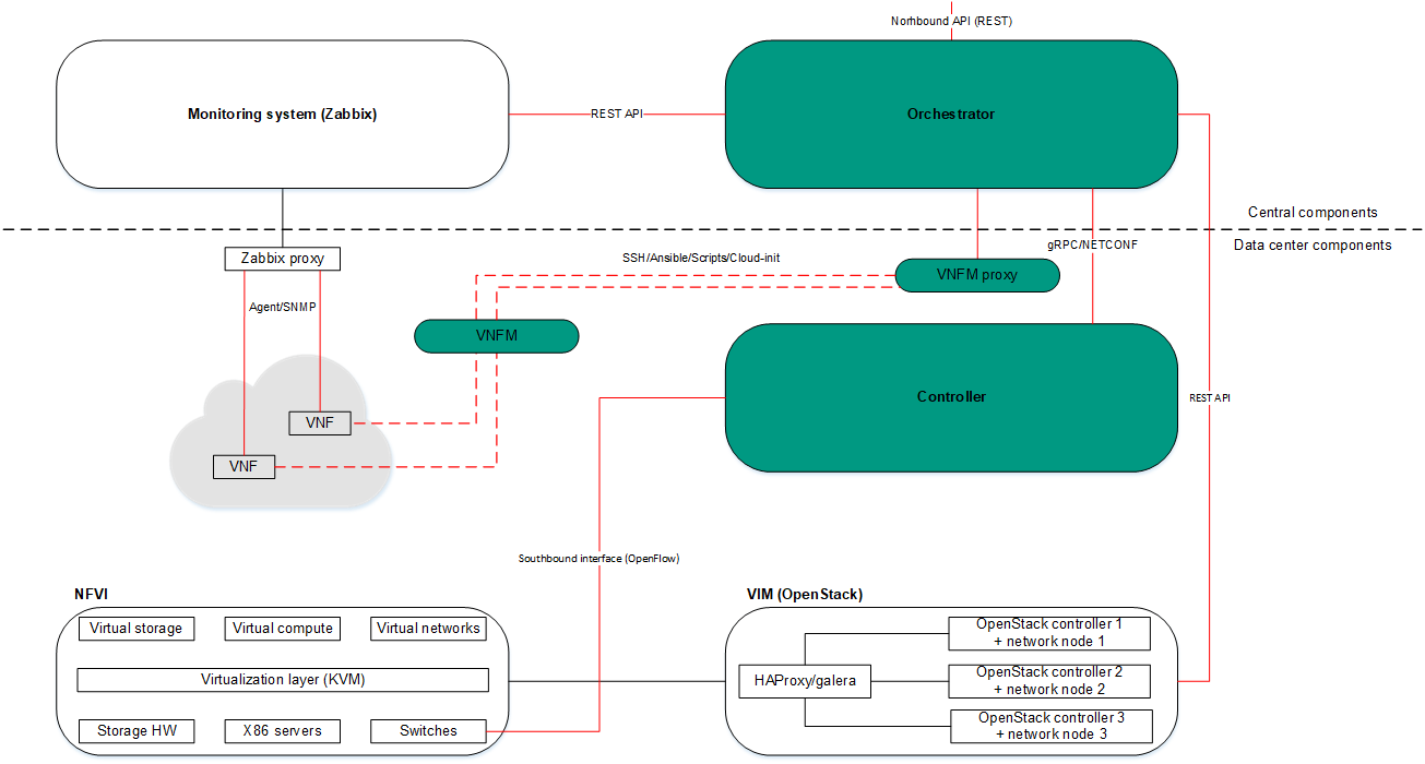
NFV infrastructure