Contents
- Deploying Kaspersky SD-WAN
- Redundancy of solution components
- About the installation archive
- About the attended, unattended, and partially attended action modes
- Preparing the administrator device
- Managing passwords
- Preparing the configuration file
- Replacing the graphics of the orchestrator web interface
- Replacement of a failed controller node
- Upgrading Kaspersky SD-WAN
- Removing Kaspersky SD-WAN
Deploying Kaspersky SD-WAN
You can deploy Kaspersky SD-WAN using the knaas-installer_<version information> installation archive that is part of the distribution kit.
Before following this procedure, you must prepare a solution deployment scenario. If you have any problems with preparing a deployment scenario, we recommend contacting Kaspersky Technical Support.
A solution deployment scenario consists of the following steps:
- Preparing the administrator device
Prepare the administrator device for solution deployment. You can use a local or remote virtual machine, or a personal computer as the administrator device. When deploying a Kaspersky SD-WAN testbed in accordance with the all-in-one deployment scenario, you must use a virtual machine as the administrator device.
- Ensuring network connectivity between the administrator device and solution components
Ensure network connectivity between the administrator device and the virtual machines or physical servers on which you want to deploy Kaspersky SD-WAN components. If you plan to deploy multiple nodes of solution components, make sure that the links between virtual machines or physical servers satisfy the hardware and software requirements.
- Manually generating passwords
If necessary, manually generate passwords to ensure the security of Kaspersky SD-WAN components and their SSL certificates.
- Preparing the configuration file
Prepare the configuration file in accordance with the chosen deployment scenario. You can use example configuration files for typical deployment scenarios in the /inventory/external/pnf and /inventory/external/vnf directories of the installation archive.
- Replacing the graphics of the orchestrator web interface
If necessary, replace the graphics of the orchestrator web interface. For example, you can replace the image that is displayed in the background when an error occurs while logging into the orchestrator web interface.
- Deploying Kaspersky SD-WAN
Do the following on the administrator device:
- Accept the End User License Agreement by running the following command:
export KNAAS_EULA_AGREED="true" - Go to the directory with the extracted installation archive.
- If you want to deploy Kaspersky SD-WAN in attended mode, do one of the following:
- If you have generated passwords manually, run the command:
ansible-playbook -i inventory/generic -e "@<path to configuration file>" -e "@inventory/external/images.yml" -K --ask-vault-pass knaas/knaas-install.ymlWhen running the command, enter the root account password and the generated master password.
- If you have not generated passwords manually, run the command:
ansible-playbook -i inventory/generic -e "@<path to configuration file>" -e "@inventory/external/images.yml" -K knaas/knaas-install.yml
- If you have generated passwords manually, run the command:
- If you want to deploy Kaspersky SD-WAN in unattended mode, do one of the following:
We only recommend using this mode in a trusted environment because it makes intercepting your passwords easy for a malicious actor.
- If you have generated passwords manually, run the command:
ansible-playbook -i inventory/generic -e "@<path to configuration file>" -e "@inventory/external/images.yml" -e "ansible_become_password=yourSudoPassword" --vault-password-file ./passwords/vault_password.txt knaas/knaas-install.yml - If you have not generated passwords manually, run the command:
ansible-playbook -i inventory/generic -e "@<path to configuration file>" -e "@inventory/external/images.yml" -e "ansible_become_password=yourSudoPassword" knaas/knaas-install.yml
- If you have generated passwords manually, run the command:
- Accept the End User License Agreement by running the following command:
The Kaspersky SD-WAN components are deployed on the virtual machines or physical servers that you specified in the configuration file. A successful deployment message is displayed in the console of the administrator device.
If a network connectivity issue occurs with one of the virtual machines or physical servers during the deployment of solution components, an error message is displayed in the administrator device console, and the solution is not deployed. In that case, you need to restore network connectivity, clean up the virtual machines or physical servers, and then run the deployment command again.
Redundancy of solution components
About redundancy schemes for solution components
Kaspersky SD-WAN supports two deployment scenarios for solution components:
- In the N+1 deployment scenario, you deploy two nodes of the solution component. If one node fails, the second node provides the functionality of the solution component.
- In the 2N+1 deployment scenario, you deploy multiple nodes of the solution component. One node is the primary node and the rest are secondary nodes. If the primary node fails, a randomly chosen secondary node takes its place. This redundancy scheme allows solution components to remain operational even when multiple failures occur in a row.
The table below lists the solution components and the deployment scenarios that are applicable to them.
Solution component |
Redundancy scheme |
Database of the Zabbix monitoring system |
2N+1 |
Zabbix server |
N+1 |
Frontend part of the Zabbix monitoring system |
N+1 |
Zabbix proxy server |
N+1 |
MongoDB database |
2N+1 |
Redis database:
|
2N+1 |
Controller |
2N+1 |
Frontend part of the solution |
N+1 |
Orchestrator |
N+1 |
Virtual Network Function Manager |
N+1 |
Virtual Network Function Manager proxy |
N+1 |
You can specify the number of nodes you want to deploy for each solution component in the configuration file.
When you configure the deployment settings for the MongoDB database or the controller node in accordance with the 2N+1 deployment scenario, the last node you specify becomes the arbiter node. The arbiter node is linked to other nodes and is used to choose the primary node. A node that has lost contact with the arbiter node enters standby mode. One of the nodes that have retained contact with the arbiter node stays or becomes the primary node. An arbiter node cannot become a primary node and does not store data.
Failure scenarios of solution component nodes
The figure below shows a diagram of Kaspersky SD-WAN deployed on three virtual machines in a data center. The diagram uses the following symbols:
- 'www' is the frontend part of the solution
- 'orc' is the orchestrator
- 'mongo' is the MongoDB database
- 'redis-m' is a Redis replica server
- 'redis-s' is a Redis Sentinel system
- 'vnfm-proxy' is a virtual network functions manager proxy
- 'vnfm' is a Virtual Network Function Manager
- 'ctl' is the controller and its database
- 'zabbix-www' is the frontend part of the Zabbix monitoring system
- 'zabbix-proxy' is the Zabbix proxy server
- 'zabbix-srv' is the Zabbix server
- 'zabbix-db' is the database of the Zabbix monitoring system
- 'syslog' is the Syslog server
Users and CPE devices gain access to the web interface of the orchestrator and the web interface of the Zabbix monitoring system using a virtual IP address. The virtual IP address is assigned to virtual machine 1.
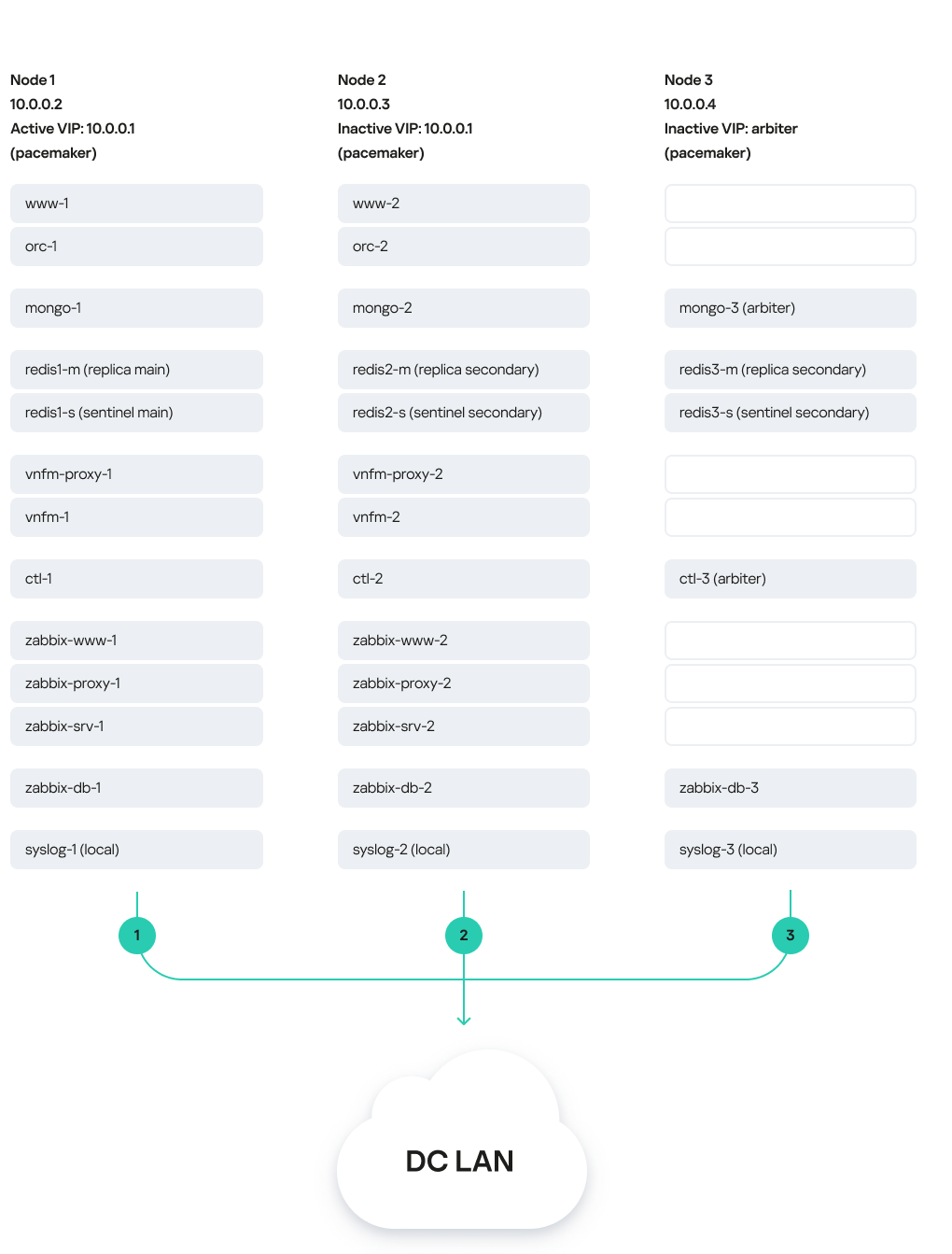
Solution deployed on three virtual machines
In this deployment scenario, the following failure modes are possible:
- Failure of virtual machine 1 or its link.
- Failure of virtual machine 2 or 3, or its link.
- Simultaneous failure of virtual machines 1 and 3 or 2 and 3, or their links.
- Simultaneous failure of virtual machines 1 and 2
About the installation archive
The knaas-installer_<version information> installation archive has the TAR format and is used for solution deployment. You can download the installation archive from the root directory of the distribution kit. The installation archive has the following structure:
We do not recommend editing system files because this may cause errors when deploying the solution.
- ansible.cfg file is a system file with Ansible settings.
- CHANGELOG.md is the file change log in YAML format.
- /docs contains the installation archive documentation.
- /images contains images of the solution components.
- /inventory:
- /external:
- /pnf contains example configuration files for typical solution deployment scenarios with the controller as a physical network function.
- /vnf contains example configuration files for typical solution deployment scenarios with the controller as a virtual network function.
- /external:
- /generic contains common system files.
- /knaas contains system files with playbooks for deploying the solution.
- /oem contains default graphics of the orchestrator web interface.
- /pnfs contains physical network functions for deployment of one, three, or five controller nodes.
- README.md contains instructions for deploying the solution using the installation archive.
- requirements.txt is a system file with Python requirements.
About the attended, unattended, and partially attended action modes
When you perform actions on the administrator device when deploying Kaspersky SD-WAN, you may need to enter the root password as well as the master password. How the passwords are entered depends on the mode in which you are performing the action. The following action modes are supported:
- In the attended mode, an employee must take part in the action. To perform an action, you must manually enter the root password and the master password. This is the safest mode that avoids saving any passwords on the administrator device.
- In the unattended mode, the action is performed without involving an employee. To perform an action, the root password and the master password are entered automatically. In this mode, you can run automated tests.
We only recommend using this mode in a trusted environment because it makes intercepting your passwords easy for a malicious actor.
- In the partially attended mode, the action is performed with partial involvement of an employee. When performing an action, you must enter the root password, but the master password is entered automatically.
Preparing the administrator device
You can use a local or remote virtual machine, or a personal computer as the administrator device. When deploying a Kaspersky SD-WAN testbed in accordance with the all-in-one deployment scenario, you must use a virtual machine as the administrator device.
If you experience any problems while preparing the administrator device, we recommend contacting Kaspersky Technical Support.
To prepare the administrator device:
- Make sure the administrator device satisfies the hardware and software requirements.
- Make sure that the same root account is used on the administrator device and the virtual machines or physical servers on which you want to deploy Kaspersky SD-WAN components. After deploying the solution, you can use a different root account on the virtual machines or physical servers.
- Download the knaas-installer_<version information> installation archive from the root directory of the distribution kit and extract the installation archive on the administrator device.
- Go to the directory with the extracted installation archive and prepare the administrator device:
- Make sure the pip package management tool is installed by running the command:
python3 -m pip -V - If the pip package management tool is not present, do one of the following:
- If the administrator device is running Ubuntu:
apt-get install python3-pip - If the administrator device is running RED OS 8:
yum install python3-pip
- If the administrator device is running Ubuntu:
- Install the Ansible tool and its dependencies:
python 3 -m pip install -U --user -r requirements.txt - Update the PATH variable:
echo 'export PATH=$PATH:$HOME/.local/bin' >> ~/.bashrcsource ~/.bashrc
- Verify that the Ansible tool is ready for use:
ansible --version - Install the operating system packages for Kaspersky SD-WAN deployment on the administrator device:
ansible-playbook -K knaas/utilities/toolserver_prepare/bootstrap.ymlEnter the root password when running the command.
You only need to complete this step when initially deploying the solution.
- Make sure the pip package management tool is installed by running the command:
- Make sure the administrator device is ready for use:
- Restart the administrator device.
- Go to the extracted installation archive and start the automatic check of the administrator device:
ansible-playbook knaas/utilities/pre-flight.yml
- If you want to deploy Kaspersky SD-WAN on multiple virtual machines or physical servers:
- Make sure SSH keys have been generated on the administrator device. If the SSH keys do not exist, generate them.
- Place the SSH keys on virtual machines or physical servers:
ssh-copy-id user@<IP address of the virtual machine or physical server>
If you are deploying a Kaspersky SD-WAN testbed in accordance with the all-in-one deployment scenario, skip this step.
The administrator device is prepared for Kaspersky SD-WAN deployment.
Page topManaging passwords
Passwords help ensure the security of deployed Kaspersky SD-WAN components. You can manually generate the passwords. If you do not manually generate the passwords, they are generated automatically when you deploy the solution.
Passwords are contained in the following files:
- keystore.yml contains passwords of Kaspersky SD-WAN components and their SSL certificates.
- vault_password.txt contains the master password.
We recommend storing password files in a protected directory because they can be used to gain access to the deployed solution.
After deployment, the generated passwords are automatically placed in the Docker containers of Kaspersky SD-WAN components. Solution components exchange passwords when interacting with each other.
Manually generating passwords
To manually generate the passwords:
- Create the /passwords directory on the administrator device. Specify the path to the created directory in the
externalsection of the configuration file using thevault_password_dirnamesetting. - Create a keystore.yml file and in that file, specify the passwords using the following settings:
ZABBIX_DB_SECRETis the root password of the Zabbix monitoring system database.MONGO_ADMIN_SECRETis the administrator password of the MongoDB database.MONGO_USER_SECRETis the user password of the MongoDB database. This password is used by the orchestrator.CTL_CERT_SECRETis the password of the controller SSL certificate.ORC_CERT_SECRETis the password of the orchestrator SSL certificate.ORC_ENC_SECRETis the password for encrypting confidential data in the MongoDB database. Minimum length: 32 characters.VNFM_CERT_SECRETis the password of the VNFM SSL certificate.
For all passwords except
ORC_ENC_SECRET, we recommend specifying at least 16 characters. - Create the vault_password.txt file and in that file, specify the master password.
- Encrypt the keystore.yml file:
- If you want to encrypt the keystore.yml file in attended mode:
ansible-vault encrypt --ask-vault-pass keystore.yml - If you want to encrypt the keystore.yml file in unattended mode:
ansible-vault encrypt --vault-password-file vault_password.txt keystore.yml
- If you want to encrypt the keystore.yml file in attended mode:
The passwords are generated and encrypted.
Changing passwords
To change the passwords:
- Decrypt the keystore.yml file:
- If you want to decrypt the keystore.yml file in attended mode:
ansible-vault decrypt --vault-password-file vault_password.txt keystore.yml - If you want to decrypt the keystore.yml file in unattended mode:
ansible-vault encrypt --ask-vault-pass keystore.yml
- If you want to decrypt the keystore.yml file in attended mode:
- Change the following passwords in the keystore.yml file:
ZABBIX_DB_SECRETis the root password of the Zabbix monitoring system database.MONGO_ADMIN_SECRETis the administrator password of the MongoDB database.MONGO_USER_SECRETis the user password of the MongoDB database. This password is used by the orchestrator.CTL_CERT_SECRETis the password of the controller SSL certificate.ORC_CERT_SECRETis the password of the orchestrator SSL certificate.ORC_ENC_SECRETis the password for encrypting confidential data in the MongoDB database. Minimum length: 32 characters.VNFM_CERT_SECRETis the password of the VNFM SSL certificate.
For all passwords except
ORC_ENC_SECRET, we recommend specifying at least 16 characters. - Encrypt the keystore.yml file:
- If you want to encrypt the keystore.yml file in attended mode:
ansible-vault encrypt --ask-vault-pass keystore.yml - If you want to encrypt the keystore.yml file in unattended mode:
ansible-vault encrypt --vault-password-file vault_password.txt keystore.yml
- If you want to encrypt the keystore.yml file in attended mode:
The passwords are changed and encrypted.
Page topPreparing the configuration file
Specify the Kaspersky SD-WAN deployment settings in the YAML configuration file on the administrator device. The path to the configuration file must be specified when deploying the solution. You can use example configuration files for typical deployment scenarios in the inventory/external/pnf and inventory/external/vnf directories of the installation archive.
The configuration file consists of two main sections:
- The
nodessection specifies virtual machines or physical servers for deploying Kaspersky SD-WAN components. When deploying the solution to virtual machines or physical servers, iptables rules for interaction between solution components are automatically generated. - The
externalsection specifies Kaspersky SD-WAN deployment settings.
We do not recommend changing the default settings.
The nodes section has the following structure:
Section/setting |
Description |
||
|---|---|---|---|
|
Deployment settings of virtual machine or physical server. |
||
|
|
IP address of the virtual machine or physical server. Enter a value in the
|
|
|
Virtual IP address of the virtual machine or physical server. Enter a value in the
This setting must be specified for all virtual machines or physical servers on which you plan to use virtual IP addresses. |
||
|
Settings for connecting Docker containers of Kaspersky SD-WAN components to the local virtual network of the virtual machine or physical server. |
||
|
|
The first three octets of the local virtual network IP address. Default value:
You can change the first three octets of the default IP address if they overlap with your address space. |
|
|
Operating mode of the local virtual network. Possible values:
|
||
|
Name of the virtual machine or physical server interface for connecting Docker containers over the L2 network, for example:
This parameter must be specified if for |
||
|
VLAN tag of the L2 network. Enter a value in the range of 1 to 4095. If you do not want to use a VLAN tag, enter This parameter must be specified if for |
||
|
Settings for connecting Docker containers of Kaspersky SD-WAN components to the management virtual network or physical server of the virtual machine. |
||
|
|
The first three octets of the management virtual network IP address. Default value:
You can change the first three octets of the default IP address if they overlap with your address space. |
|
|
Operating mode of the management virtual network. Possible values:
|
||
|
Name of the virtual machine or physical server interface for connecting Docker containers over the L2 network, for example:
This parameter must be specified if for |
||
|
VLAN tag of the L2 network. Enter a value in the range of 1 to 4095. If you do not want to use a VLAN tag, enter This parameter must be specified if for |
||
The external section has the following structure:
Section/setting |
Description |
|||
|
Path to the /passwords directory on the administrator device with manually generated passwords. If you do not generate passwords manually, they are automatically generated during solution deployment and placed in the /passwords directory of the extracted installation archive on the administrator device. |
|||
|
Name of the user account on the administrator device and on virtual machines or physical servers for running playbooks during solution deployment. |
|||
|
Settings of SSL certificates of Kaspersky SD-WAN components. |
|||
|
|
Information that is added to SSL certificates. |
||
|
|
IP addresses that are added to SSL certificates. Specify a list of values in the
|
||
|
Domain names that are added to SSL certificates. Specify a list of values, for example:
|
|||
|
Path to the directory on the administrator device that contains manually generated SSL certificates. If you do not generate SSL certificates manually, they are automatically generated during solution deployment and placed in the /ssl directory of the extracted installation archive on the administrator device. |
|||
|
Path to the directory on the virtual machines or physical servers that contains manually generated SSL certificates. If you do not generate SSL certificates manually, they are automatically generated during solution deployment and placed in the /ssl directory on virtual machines or physical servers. |
|||
|
Syslog server settings. |
|||
|
|
Amount of RAM in megabytes for Docker containers of the Syslog server. |
||
|
Amount of RAM in gigabytes for the Syslog server logs. |
|||
|
Deploying a Syslog server on virtual machines or physical servers. Possible values:
|
|||
|
Settings of the Zabbix monitoring system. For details, please refer to the official documentation of the Zabbix solution. |
|||
|
|
Web address of the Syslog server to which Docker containers of the Zabbix monitoring system send logs. Enter a value in the
You can specify Syslog server settings in the |
||
|
Amount of RAM in megabytes for Docker containers of the Zabbix monitoring system database. |
|||
|
Amount of RAM in megabytes for Docker containers of the Zabbix server. |
|||
|
Amount of RAM in megabytes for Docker containers of the Zabbix monitoring system front end. |
|||
|
Amount of RAM in megabytes for Docker containers of the Zabbix proxy server. |
|||
|
Amount of RAM in gigabytes for the Zabbix monitoring system cache. Enter a value in the
|
|||
|
Deployment settings of Zabbix monitoring system nodes. You can deploy one Zabbix monitoring system node without high availability or three nodes with high availability. |
|||
|
|
IP address of the virtual machine or physical server from the
|
||
|
Deployment settings of the Zabbix monitoring system database. |
|||
|
|
Host name of the Zabbix monitoring system database. Default value: |
||
|
Deployment of the database of the Zabbix monitoring system on a virtual machine or physical server. Possible values:
|
|||
|
Deployment settings of the Zabbix server. When deploying three nodes of the Zabbix monitoring system, you only need to specify these settings for two of the nodes. |
|||
|
|
Host name of the Zabbix server. Default value: |
||
|
Deploying the Zabbix server on a virtual machine or physical server. Possible values:
|
|||
|
Deployment settings of the frontend part of the Zabbix monitoring system. When deploying three nodes of the Zabbix monitoring system, you only need to specify these settings for two of the nodes. |
|||
|
|
Host name of the frontend part of the Zabbix monitoring system. Default value: |
||
|
Deployment of the frontend part of the Zabbix monitoring system on a virtual machine or physical server. Possible values:
|
|||
|
Deployment settings of the Zabbix proxy server. When deploying three nodes of the Zabbix monitoring system, you only need to specify these settings for two of the nodes. |
|||
|
|
Host name of the Zabbix proxy server. Default value: |
||
|
Deploying the Zabbix proxy server on a virtual machine or physical server. Possible values:
|
|||
|
MongoDB database settings. For details, please refer to the official documentation of the MongoDB database. |
|||
|
|
Web address of the Syslog server to which Docker containers of the MongoDB database send logs. Enter a value in the
You can specify Syslog server settings in the |
||
|
Amount of RAM in megabytes for Docker containers of the MongoDB database. |
|||
|
Deployment settings of MongoDB database nodes. You can deploy one MongoDB database node without high availability or three nodes with high availability. If you deploy three MongoDB database nodes, the last node becomes the arbiter node. |
|||
|
|
Host name of the MongoDB database. Default value: |
||
|
Deploying the MongoDB database on a virtual machine or physical server. Possible values:
|
|||
|
IP address of the virtual machine or physical server from the
|
|||
|
Redis database settings. For details, please refer to the official documentation of the Redis database. |
|||
|
|
Web address of the Syslog server to which Docker containers of the Redis database send logs. Enter a value in the
You can specify Syslog server settings in the |
||
|
Amount of RAM in megabytes for Docker containers of the Redis database. |
|||
|
Deployment settings for nodes of the Redis replica server. You can deploy one Redis replica server node without high availability or three nodes with high availability. |
|||
|
|
Host name of the Redis replica server. Default value: |
||
|
Deploying the Redis replica server on a virtual machine or physical server. Possible values:
|
|||
|
IP address of the virtual machine or physical server from the
|
|||
|
Deployment settings of Redis Sentinel system nodes. If you are deploying three Redis replica server nodes with high availability, you also need to deploy three nodes of the Redis Sentinel system. |
|||
|
|
Host name of the Redis Sentinel system. Default value: |
||
|
Deploying the Redis Sentinel system on a virtual machine or physical server. Possible values:
|
|||
|
IP address of the virtual machine or physical server from the
|
|||
|
Deployment settings of the controller. To deploy an SD-WAN instance for a tenant, you need to deploy the controller as a physical network function. |
|||
|
|
Settings for tenants for which you are deploying SD-WAN instances. |
||
|
Name of the tenant. |
|||
|
|
Creating a tenant and deploying the controller on a virtual machine or physical server. Possible values:
|
||
|
The first three octets of the IP address of the controller's virtual network. Enter a value in the
When deploying a Kaspersky SD-WAN testbed in accordance with the all-in-one deployment scenario, the value of this setting may be the same as the value of the |
|||
|
The first three octets of the IP address of the controller's management virtual network. Enter a value in the
|
|||
|
Deployment settings of the controller. You can deploy one controller node without high availability, or alternatively, three or five nodes with high availability. If you deploy three or five controller nodes, the last node becomes the arbiter node. |
|||
|
Host name of the controller node. Default value: |
|||
|
|
IP address of the virtual machine or physical server from the
|
||
|
Amount of RAM in megabytes for Docker containers of the controller. |
|||
|
RAM settings of the Java virtual machine. |
|||
|
|
The minimum amount of heap memory that the Java VM can allocate to the controller. Enter a value in one of the following formats:
We recommend specifying a value half as large as the |
||
|
The maximum amount of heap memory that the Java VM can allocate to the controller. Enter a value in one of the following formats:
We recommend specifying a value half as large as the |
|||
|
The maximum amount of direct memory that the Java VM can allocate to the controller. Enter a value in one of the following formats:
We recommend specifying a value half as large as the |
|||
|
Web address of the Syslog server to which Docker containers of the controller send logs. Enter a value in the
You can specify Syslog server settings in the |
|||
|
Settings of the frontend part of the solution. |
|||
|
|
Web address of the Syslog server to which Docker containers of the frontend part of the solution send logs. Enter a value in the
You can specify Syslog server settings in the |
||
|
Amount of RAM in megabytes for Docker containers of the frontend part of the solution. |
|||
|
Display settings of the graphics of the orchestrator web interface This section lets you change the graphics of the orchestrator web interface. |
|||
|
|
Replacing the default graphics of the orchestrator web interface Possible values:
|
||
|
Path to the directory on the administrator device with the graphics of the orchestrator web interface. You can find the default graphics of the orchestrator web interface in the /oem directory of the extracted installation archive on the administrator device. |
|||
|
Path to the directory on virtual machines or physical servers with the graphics of the orchestrator web interface. |
|||
|
The title that is displayed in the background when logging into the orchestrator web interface. Default value: |
|||
|
The web address that is displayed at the lower part of the orchestrator web interface. Default value: |
|||
|
The default graphics for the orchestrator web interface are replaced with the ones that you placed in this directory on the administrator device. Possible values:
In the |
|||
|
Deployment settings of nodes of the frontend part of the solution. You can deploy one node of the frontend part of the solution without high availability or two nodes with high availability. |
|||
|
|
Host name of the frontend part of the solution. Default value: |
||
|
Deployment of the frontend part of the solution on a virtual machine or physical server. Possible values:
|
|||
|
IP address of the virtual machine or physical server from the
|
|||
|
Orchestrator settings. |
|||
|
|
Web address of the Syslog server to which Docker containers of the orchestrator send logs. Enter a value in the
You can specify Syslog server settings in the |
||
|
Amount of RAM in megabytes for Docker containers of the orchestrator. |
|||
|
RAM settings of the Java virtual machine. |
|||
|
|
The minimum amount of heap memory that the Java VM can allocate to the orchestrator. Enter a value in one of the following formats:
We recommend specifying a value half as large as the |
||
|
The maximum amount of heap memory that the Java VM can allocate to the orchestrator. Enter a value in one of the following formats:
We recommend specifying a value half as large as the |
|||
|
Deployment settings of orchestrator nodes. You can deploy one node of the orchestrator without high availability or two nodes with high availability. |
|||
|
|
Host name of the orchestrator. Default value: |
||
|
Deploying the orchestrator on a virtual machine or physical server. Possible values:
|
|||
|
IP address of the virtual machine or physical server from the
|
|||
|
Settings of the Virtual Network Function Manager. |
|||
|
|
Web address of the Syslog server to which Docker containers of the Virtual Network Function Manager send logs. Enter a value in the
You can specify Syslog server settings in the |
||
|
Amount of RAM in megabytes for Docker containers of the orchestrator. |
|||
|
RAM settings of the Java virtual machine. |
|||
|
|
The minimum amount of heap memory that the Java VM can allocate to the Virtual Network Function Manager. Enter a value in one of the following formats:
We recommend specifying a value half as large as the |
||
|
The maximum amount of heap memory that the Java VM can allocate to the Virtual Network Function Manager. Enter a value in one of the following formats:
We recommend specifying a value half as large as the |
|||
|
Deployment settings of Virtual Network Function Manager nodes. You can deploy one Virtual Network Function Manager node without high availability or two nodes with high availability. |
|||
|
|
Host name of the Virtual Network Function Manager. Default value: |
||
|
Deploying the Virtual Network Function Manager on a virtual machine or physical server. Possible values:
|
|||
|
IP address of the virtual machine or physical server from the
|
|||
|
Settings of the Proxy Virtual Network Function Manager. |
|||
|
|
Web address of the Syslog server to which Docker containers of the Proxy Virtual Network Function Manager send logs. Enter a value in the
You can specify Syslog server settings in the |
||
|
Amount of RAM in megabytes for Docker containers of the Proxy Virtual Network Function Manager. |
|||
|
Deployment settings of Proxy Virtual Network Function Manager nodes. You can deploy one Proxy Virtual Network Function Manager node without high availability or two nodes with high availability. |
|||
|
|
Host name of the Proxy Virtual Network Function Manager. Default value: |
||
|
Deploying the proxy Virtual Network Function Manager on a virtual machine or physical server. Possible values:
|
|||
|
IP address of the virtual machine or physical server from the
|
|||
Replacing the graphical elements of the orchestrator web interface
To replace the graphics of the orchestrator web interface:
- Configure the frontend part of the solution in the
wwwsection of the configuration file. - On the administrator's device, go to the /oem directory of the extracted installation archive. This directory contains the default graphics of the orchestrator web interface. You can replace the following files:
- favicon.png and favicon.svg is the icon that is displayed on the orchestrator web interface tab.

- login_logo.svg is the icon that is displayed in the upper part of the window when logging in to the orchestrator web interface.
- logo_activation.svg is the icon that is displayed during the automatic registration of a CPE device.
- logo.svg and title.svg are the icon and title that are displayed in the upper part of the navigation pane of the orchestrator web interface.
- favicon.png and favicon.svg is the icon that is displayed on the orchestrator web interface tab.
Replacement of a failed controller node
You can deploy a new controller node to replace a controller node that has failed beyond repair. If a controller node fails while in a cluster with other nodes, the new controller node is automatically added to that cluster and synchronized with the existing nodes.
Before running this script, make sure that the IP address of the virtual machine or physical server on which you are deploying the new controller node is the same as the IP address of the virtual machine or physical server where the failed controller node was deployed. You specified the IP addresses of the virtual machines or physical servers for deployment of controller nodes when you deployed the solution, in the ctl section of the configuration file.
The scenario for replacing a failed controller node involves the following steps:
- Preparing the administrator device
Prepare the administrator device for deployment of the new controller node. You can use a local or remote virtual machine, or a personal computer as the administrator device. When deploying a Kaspersky SD-WAN testbed in accordance with the all-in-one deployment scenario, you must use a virtual machine as the administrator device.
- Ensuring network connectivity between the administrator device, solution components, and the new controller node
Ensure network connectivity between the administrator device, solution components, and the virtual machine or physical server on which you want to deploy the new controller node. You must make sure that the links between virtual machines or physical servers satisfy the hardware and software requirements.
- Deploying a controller node
Do the following on the administrator device:
- Accept the End User License Agreement by running the following command:
export KNAAS_EULA_AGREED="true" - Go to the directory with the extracted installation archive.
- If you want to deploy the new controller node in attended mode, do one of the following:
- If you have generated passwords manually while deploying the solution, run the following command:
ansible-playbook -i inventory/generic -e "@<path to configuration file>" -e "@inventory/external/images.yml" -K --ask-vault-pass knaas/knaas-install.ymlWhen running the command, enter the root account password and the generated master password.
- If you have not generated passwords manually while deploying the solution, run the following command:
ansible-playbook -i inventory/generic -e "@<path to configuration file>" -e "@inventory/external/images.yml" -K knaas/knaas-install.yml
- If you have generated passwords manually while deploying the solution, run the following command:
- If you want to deploy the controller node in unattended mode, do one of the following:
We only recommend using this mode in a trusted environment because it makes intercepting your passwords easy for a malicious actor.
- If you have generated passwords manually while deploying the solution, run the following command:
ansible-playbook -i inventory/generic -e "@<path to configuration file>" -e "@inventory/external/images.yml" -e "ansible_become_password=yourSudoPassword" --vault-password-file ./passwords/vault_password.txt knaas/knaas-install.yml - If you have not generated passwords manually while deploying the solution, run the following command:
ansible-playbook -i inventory/generic -e "@<path to configuration file>" -e "@inventory/external/images.yml" -e "ansible_become_password=yourSudoPassword" knaas/knaas-install.yml
- If you have generated passwords manually while deploying the solution, run the following command:
- Accept the End User License Agreement by running the following command:
The new controller node is deployed to replace the failed controller node. A successful deployment message is displayed in the console of the administrator device.
If a network connectivity problem occurs with a virtual machine or physical server while deploying the controller node, an error is displayed in the console of the administrator device, and the new controller node is not deployed. In that case, you need to restore network connectivity, clean up the virtual machine or physical server, and then run the deployment command again.
Upgrading Kaspersky SD-WAN
Before updating Kaspersky SD-WAN, make sure that none of the CPE devices have the Error status. You can view the status of CPE devices in the CPE device table. We also recommend creating backup copies of solution components before updating Kaspersky SD-WAN:
- If your solution components are deployed on virtual machines, take snapshots of the virtual machines. After updating Kaspersky SD-WAN, you can delete the snapshots of the virtual machines. For details on how to take snapshots of virtual machines, please refer to the official documentation of your virtualization environments.
- If your solution components are deployed on physical servers, you need to make backups of hard drives of the physical servers.
The Kaspersky SD-WAN upgrade scenario involves the following steps:
- Preparing the administrator device
Prepare the administrator device for solution upgrade. You can use a local or remote virtual machine, or a personal computer as the administrator device. When deploying a Kaspersky SD-WAN testbed in accordance with the all-in-one deployment scenario, you must use a virtual machine as the administrator device.
- Preparing the configuration file
Set up the configuration file in accordance with the changes that have been made to the new version of Kaspersky SD-WAN. You can view the changes in the in the CHANGELOG.md file in the root directory of the installation archive.
When upgrading Kaspersky SD-WAN, make sure that you keep the files with passwords and SSL certificates.
- Upgrading Kaspersky SD-WAN
Upgrade Kaspersky SD-WAN in one of the following ways:
- If you want to upgrade the solution in attended mode:
ansible-playbook -i inventory/generic -e "@<path to configuration file>" -e "@inventory/external/images.yml" -K --ask-vault-pass knaas/knaas-install.ymlWhen running the command, enter the password of the root account on the administrator device and the generated master password.
- If you want to upgrade the solution in partially attended mode:
ansible-playbook -i inventory/generic -e "@<path to configuration file>" -e "@inventory/external/images.yml" -K --vault-password-file ./passwords/vault_password.txt knaas/knaas-install.ymlEnter the root password o the administrator device when running the command.
- If you want to upgrade the solution in unattended mode:
ansible-playbook -i inventory/generic -e "@<path to configuration file>" -e "@inventory/external/images.yml" -e "ansible_become_password=yourSudoPassword" --vault-password-file ./passwords/vault_password.txt knaas/knaas-install.yml
- If you want to upgrade the solution in attended mode:
The Kaspersky SD-WAN components are upgraded on the virtual machines or physical servers that you specified in the configuration file. A successful upgrade message is displayed in the console of the administrator device.
If a network connectivity issue occurs with one of the virtual machines or physical servers during the upgrade of solution components, an error message is displayed in the administrator device console, and the solution is not upgraded. In that case, you need to restore network connectivity and then run the upgrade command again.
After upgrading the solution, you must clear your Bash command history.
Removing Kaspersky SD-WAN
The removal of Kaspersky SD-WAN cannot be rolled back.
To remove Kaspersky SD-WAN:
- On the administrator device, go to the extracted installation archive.
- Remove Kaspersky SD-WAN in one of the following ways:
- If you want to remove the solution in attended mode:
ansible-playbook -i inventory/generic -e "@<path to configuration file>" -e "@inventory/external/images.yml" -K knaas/knaas-teardown.yml - If you want to remove the solution in unattended mode:
ansible-playbook -i inventory/generic -e "@<path to configuration file>" -e "@inventory/external/images.yml" -e "ansible_become_password=yourSudoPassword" knaas/knaas-teardown.yml
- If you want to remove the solution in attended mode:
Kaspersky SD-WAN components are removed from the virtual machines or physical servers. A successful removal message is displayed in the console of the administrator device.
If a network connectivity issue occurs with one of the virtual machines or physical servers during the removal of solution components, an error message is displayed in the administrator device console, and the solution is not removed. In that case, you need to restore network connectivity and then run the removal command again.