Contents
Building the examples
The examples are built using the CMake build system that is included in KasperskyOS Community Edition.
The code of the examples and build scripts are available at the following path:
/opt/KasperskyOS-Community-Edition-<version>/examples
You need to build the examples in a directory in which you have write access. For example, you can do so by copying the directory containing the example into the home directory.
Building the examples to run on QEMU
To build an example, go to the directory with the example and run this command:
Running the cross-build.sh script creates a KasperskyOS-based solution image that includes the example, and initiates startup of the example in QEMU. The kos-qemu-image solution image is located in the <name of example>/build/einit directory.
Building the examples to run on Raspberry Pi 4 B or Radxa ROCK 3A
To build an example, go to the directory with the example and run this command:
The type of image that is created by the cross-build.sh script depends on the value that you choose for the target parameter:
kos-imageThis creates a KasperskyOS-based solution image that includes the example. The
kos-imagesolution image is located in the<name of example>/build/einitdirectory.sd-imageThis creates a file system image for a bootable SD card. The following is loaded into the file system image:
kos-image, U-Boot bootloader that starts the example, and the firmware for Raspberry Pi 4 B or Radxa ROCK 3A. The source code for the U-Boot bootloader and firmware can be downloaded from the website https://github.com. The file system image filehdd.imgis saved in the directory <example name>/build.
Before running the examples on Radxa ROCK 3A, you also need to build the drivers provided as a source code in the SDK. Instructions for building drivers can be found in the descriptions of examples (README.md files).
Running examples on QEMU
Running examples on QEMU on Linux with a graphical shell
You need to run the examples in a build directory in which you have write access.
An example is run on QEMU on Linux with a graphical shell using the cross-build.sh script, which also builds the example. To run the script, go to the folder with the example and run the command:
Running examples on QEMU on Linux without a graphical shell
To run an example on QEMU on Linux without a graphical shell, go to the directory with the example, build the example and run the following commands:
Preparing Raspberry Pi 4 B to run examples
Connecting a computer and Raspberry Pi 4 B
To see the output from Raspberry Pi 4 B on a computer and to have debug capabilities, do the following:
- Connect the pins of the FT232 USB-UART converters to the corresponding GPIO pins of Raspberry Pi 4 B (see the figure below). If debugging is not necessary, all you need to do is connect one USB-UART converter for output.
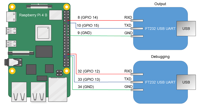
Diagram for connecting USB-UART converters and Raspberry Pi 4 B
- Connect the computer's USB ports and the USB-UART converters.
- Install PuTTY or another equivalent program. Configure the settings as follows:
bps = 115200,data bits = 8,stop bits = 1,parity = none,flow control = none. Define the USB port connected to the USB-UART converter used for receiving output from Raspberry Pi 4 B.
To allow a computer and Raspberry Pi 4 B to interact through Ethernet:
- Connect the network cards of the computer and Raspberry Pi 4 B to a switch or to each other.
- Configure the computer's network card so that its IP address is in the same subnet as the IP address of the Raspberry Pi 4 B network card (the settings of the Raspberry Pi 4 B network card are defined in the
dhcpcd.conffile, which is found at the path<example name>/resources/...).
Preparing a bootable SD card for Raspberry Pi 4 B
If the hdd.img image was created when building the example, all you have to do is write the resulting image to the SD card. To do this, connect the SD card to the computer and run the following command:
If kos-image was created when building the example, the SD card requires additional preparations before you can write the image to it. A bootable SD card for Raspberry Pi 4 B can be prepared automatically or manually. After preparing the SD card, you must copy the kos-image file from the directory <example name>/build/einit to the bootable area (FAT32 partition) of the prepared SD card.
To automatically prepare the bootable SD card, connect the SD card to the computer and run the following commands:
To manually prepare the bootable SD card:
- If a Docker container is used when working with KasperskyOS Community Edition, it must be granted access to devices in the
/devdirectory on the host system. To do so when starting the Docker container, add the following parameter to the startup command:-v /dev:/dev - Build the U-Boot bootloader for ARMv8, which will automatically run the example. To do this, run the following commands:$ sudo apt install git build-essential libssl-dev bison flex unzip parted gcc-aarch64-linux-gnu udev dosfstools pv -y $ git clone --depth 1 --branch v2022.01 https://github.com/u-boot/u-boot.git u-boot-armv8 $ cd u-boot-armv8 $ make ARCH=arm CROSS_COMPILE=aarch64-linux-gnu- rpi_4_defconfig $ echo 'CONFIG_SERIAL_PROBE_ALL=y' > ./.custom_config $ echo 'CONFIG_BOOTCOMMAND="fatload mmc 0 ${loadaddr} kos-image; bootelf ${loadaddr} ${fdt_addr}"' >> ./.custom_config $ echo 'CONFIG_PREBOOT="pci enum;"' >> ./.custom_config $ ./scripts/kconfig/merge_config.sh '.config' '.custom_config' $ make ARCH=arm CROSS_COMPILE=aarch64-linux-gnu- u-boot.bin
- Prepare the image containing the file system for the SD card.# Image will contain a boot partition of 1 GB in fat32 and three partitions of 350 MB each in ext2, ext3 and ext4, respectively. $ fs_image_name=sdcard.img $ dd if=/dev/zero of=${fs_image_name} bs=1024k count=2048 $ sudo parted ${fs_image_name} mklabel msdos $ loop_device=$(sudo losetup --find --show --partscan ${fs_image_name}) $ sudo parted ${loop_device} mkpart primary fat32 8192s 50% $ sudo parted ${loop_device} mkpart extended 50% 100% $ sudo parted ${loop_device} mkpart logical ext2 50% 67% $ sudo parted ${loop_device} mkpart logical ext3 67% 84% $ sudo parted ${loop_device} mkpart logical ext4 84% 100% $ sudo parted ${loop_device} set 1 boot on $ sudo mkfs.vfat ${loop_device}p1 $ sudo mkfs.ext2 ${loop_device}p5 $ sudo mkfs.ext3 ${loop_device}p6 $ sudo mkfs.ext4 -O ^64bit,^extent ${loop_device}p7
- Copy the U-Boot bootloader and embedded software (firmware) for Raspberry Pi 4 B to the received file system image by running the following commands:# In the following commands, the path ~/mnt/fat32 is just an example. # You can use a different path. $ mount_temp_dir=~/mnt/fat32 $ mkdir -p ${mount_temp_dir} $ sudo mount ${loop_device}p1 ${mount_temp_dir} $ git clone --depth 1 --branch 1.20220331 https://github.com/raspberrypi/firmware.git firmware $ sudo cp u-boot.bin ${mount_temp_dir}/u-boot.bin $ sudo cp -r firmware/boot/. ${mount_temp_dir}
- Fill in the configuration file for the U-Boot bootloader in the image by using the following commands:$ sudo sh -c "echo '[all]' > ${mount_temp_dir}/config.txt" $ sudo sh -c "echo 'arm_64bit=1' >> ${mount_temp_dir}/config.txt" $ sudo sh -c "echo 'enable_uart=1' >> ${mount_temp_dir}/config.txt" $ sudo sh -c "echo 'kernel=u-boot.bin' >> ${mount_temp_dir}/config.txt" $ sudo sh -c "echo 'dtparam=i2c_arm=on' >> ${mount_temp_dir}/config.txt" $ sudo sh -c "echo 'dtparam=i2c=on' >> ${mount_temp_dir}/config.txt" $ sudo sh -c "echo 'dtparam=spi=on' >> ${mount_temp_dir}/config.txt" $ sudo sh -c "echo 'device_tree_address=0x2eff5b00' >> ${mount_temp_dir}/config.txt" $ sudo sh -c "echo 'device_tree_end=0x2f0f5b00' >> ${mount_temp_dir}/config.txt" $ sudo sh -c "echo 'dtoverlay=uart5' >> ${mount_temp_dir}/config.txt" $ sudo umount ${mount_temp_dir} $ sudo losetup -d ${loop_device}
- Write the resulting image to an SD card. To do this, connect the SD card to the computer and run the following command:# In the following command, [X] is the last symbol in the name of the block device for the SD card. $ sudo pv -L 32M ${fs_image_name} | sudo dd bs=64k of=/dev/sd[X] conv=fsync
- After preparing the SD card, you must copy the
kos-imagefile from the directory<example name>/build/einitto the bootable area (FAT32 partition) of the prepared SD card.
Preparing Radxa ROCK 3A to run examples
Switching for a computer and Radxa ROCK 3A
To see the output from Radxa ROCK 3A on a computer and to have debug capabilities, do the following:
- Connect the pins of the USB-UART converters to the corresponding GPIO pins of the Radxa ROCK 3A (see the figure below). If debugging is not necessary, all you need to do is connect one USB-UART converter for output.
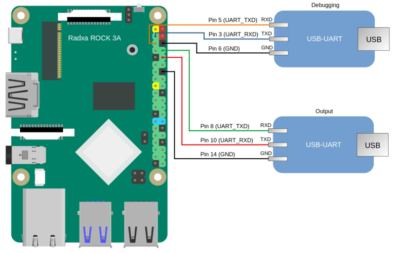
Diagram for connecting USB-UART converters and Radxa ROCK 3A
- Connect the computer's USB ports and the USB-UART converters.
- Install PuTTY or another equivalent program. Configure the settings as follows:
bps = 1500000, data bits = 8, stop bits = 1, parity = none, flow control = none. Define the USB port connected to the USB-UART converter used for receiving output from Radxa ROCK 3A.
To allow a computer and Radxa ROCK 3A to interact through Ethernet, perform the following actions:
- Connect the network cards of the computer and Radxa ROCK 3A to a switch or to each other.
- Configure the computer's network card so that its IP address is in the same subnet as the IP address of the Radxa ROCK 3A network card (the settings of the Radxa ROCK 3A network card are defined in the
dhcpcd.conffile, which is found at the path<example name>/resources/...).
Debugging programs for Radxa ROCK 3A
To debug programs running on the Radxa ROCK 3A, you must do the following:
- Include a second USB-UART converter (see the figure above).
- In the home directory of the user, create the
.gdbinitfile and add the following strings to it:set sysroot /opt/KasperskyOS-Community-Edition-<version>/sysroot-aarch64-kos add-symbol-file <path_to_debuggee>/build/einit/EinitQemu-kss/ksm.module set follow-fork-mode parent set follow-exec-mode same set detach-on-fork off set schedule-multiple on set serial baud 115200 target extended-remote /dev/ttyUSB[n] - In the
CmakeLists.txtfile in the<path_to_debuggee>/einitdirectory, add theGDBSTUB_KERNELparameter to thebuild_kos_hw_image ()command call. - Build the program. After startup and initialization, the entry
[KDBG ] Waiting for GDB connection infinitelywill appear in the output. The application will stop while it waits for the debugger to connect. - To connect the debugger, you must run gdb from the SDK:
/opt/KasperskyOS-Community-Edition-<version>/toolchain/bin/aarch64-kos-gdb. - After the debugger starts, the entry
[KDBG ] Connection to GDB was establishedwill appear in the output.For more details, refer to Preparations for debugging on the hardware platform and Initial steps of debugging on the hardware platform.
Preparing a bootable SD card for Radxa ROCK 3A
If the hdd.img image was created when building the example, all you have to do is write the resulting image to the SD card. To do this, connect the SD card to the computer and run the following command:
If kos-image was created when building the example, the SD card requires additional preparations before you can write the image to it. A bootable SD card for Radxa ROCK 3A can be prepared automatically or manually. After preparing the SD card, you must copy the kos-image file from the directory <example name>/build/einit to the bootable area (FAT32 partition) of the prepared SD card.
To automatically prepare the bootable SD card, connect the SD card to the computer and run the following commands:
Clearing the Radxa ROCK 3A flash memory
In some editions of the Radxa ROCK 3A, the flash memory may contain a bootloader that is incompatible with the card that you have prepared according to the instructions provided above.
If you see the message "SPL: failed to boot from all boot devices" when running examples on the Radxa ROCK 3A, you must clear the Radxa ROCK 3A flash memory before running the examples.
To clear the Radxa ROCK 3A flash memory:
- Download and install the tool named
rkdeveloptool.Instructions on installing this tool are provided in the documentation: https://docs.radxa.com/en/rock3/rock3a/low-level-dev/rkdeveloptool?host-os=debian#installation-for-rkdeveloptool
- Download the bootloader for interacting with the Radxa ROCK 3A: https://dl.radxa.com/rock3/images/loader/rk356x_spl_loader_ddr1056_v1.12.109_no_check_todly.bin
- Switch the Radxa ROCK 3A to
Maskrommode:- Power it off.
- Extract the SD card (and the eMMC module if present).
- Connect the computer's USB port to the ROCK 3A OTG port (upper USB 3.0 port).
- Connect the Radxa ROCK 3A pins as shown on the figure below and power on the Radxa ROCK 3A.
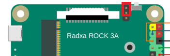
- Disconnect the pins that were connected at the previous step.
- Make sure that the Radxa ROCK 3A is in
Maskrommode by running the following command in the terminal:$: rkdeveloptool ld DevNo=1 Vid=0x2207,Pid=0x350a,LocationID=104 Maskrom
- Copy the bootloader for RAM initialization and firmware environment preparation to the Radxa ROCK 3A by running the following command in the terminal:rkdeveloptool db rk356x_spl_loader_ddr1056_v1.12.109_no_check_todly.bin
- Clear the Radxa ROCK 3A flash memory by running the following commands in the terminal:rkdeveloptool ef rkdeveloptool rd
Running examples on Raspberry Pi 4 B or Radxa ROCK 3A
To run an example on a Raspberry Pi 4 B or Radxa ROCK 3A:
- Go to the directory with the example and build the example.
- Make sure that Raspberry Pi 4 B or Radxa ROCK 3A and the bootable SD card are prepared to run examples.
- Connect the bootable SD card to the Raspberry Pi 4 B or Radxa ROCK 3A.
- Supply power to the Raspberry Pi 4 B or Radxa ROCK 3A and wait for the example to run.
The output displayed on the computer connected to Raspberry Pi 4 B or Radxa ROCK 3A indicates that the example started.
Before running the examples on Radxa ROCK 3A, you also need to build the drivers provided as a source code in the SDK. Instructions for building drivers can be found in the descriptions of examples (README.md files).
If you see the message "SPL: failed to boot from all boot devices" when running examples on the Radxa ROCK 3A, you must clear the Radxa ROCK 3A flash memory before running the examples. For more details, refer to Preparing Radxa ROCK 3A to run examples.