Contents
- Transmission of traffic between CPE devices and client devices using transport services
- Traffic packet duplication
- Scenario: Directing application traffic to a transport service
- Managing Point-to-Point (P2P) transport services
- Managing Point-to-Multipoint (P2M) transport services
- Managing Multipoint-to-Multipoint (M2M) transport services
- Managing L3 VPN transport services
- Managing IP multicast transport services
- Managing transport services in an SD-WAN instance template
- Managing transport services in a CPE template
- Traffic mirroring and forwarding between CPE devices
Transmission of traffic between CPE devices and client devices using transport services
About transport services
You can use transport services to transmit traffic between CPE devices and client devices connected to them. Transport services are built on top of segments and consist of service interfaces. Kaspersky SD-WAN supports creating the following transport services:
- L2:
- Point-to-Point (E-line in the MEF classification, hereinafter also referred to as P2P service) is a static transport service in which traffic is transmitted between two service interfaces.
- Point-to-Multipoint (E-tree in the MEF classification, hereinafter also referred to as P2M service) is a transport service in which traffic is transmitted between multiple service interfaces in accordance with a tree topology. To each service interface added to the P2M service, you must assign one of the following roles:
- Root means the service interface can send traffic to service interfaces with any role.
- Leaf means the service interface can send traffic only to service interfaces with the Root role.
- Multipoint-to-Multipoint (E-LAN in the MEF classification, hereinafter also referred to as M2M service) is a transport service in which traffic is transmitted between multiple service interfaces without a hierarchy.
The P2P service is a static transport service and does not use the MAC learning mechanism to populate the MAC table on the Controller. MAC addresses are automatically added to the MAC table on the controller when a P2P service is created or modified. The MAC address learning mechanism is used for P2M services and M2M services.
- L3 VPN (hereinafter also referred to as L3 VPN service) is a transport service in which traffic is routed between multiple L3 interfaces, which are mapped to service interfaces or M2M services.
- IP multicast (hereinafter also referred to as IP multicast service) is a transport service in which a multicast tree is built for traffic distribution between multiple service interfaces.
When creating or editing transport services, you can add backup service interfaces. A backup service interface makes it possible to continue data transfer in the event of a failure of the primary service interface. Backup and primary service interfaces can be created on the same CPE device or on different CPE devices.
Traffic can be mirrored or forwarded between service interfaces of CPE devices. In this case, service interfaces can be added to the transport service.
Managing transport services in an SD-WAN instance template or in a CPE template
You can create P2M services and M2M services as well as L3 VPN services in an SD-WAN instance template and then use it when deploying an SD-WAN instance. Transport services created in the SD-WAN instance template are automatically created for the deployed SD-WAN instance. In this way, you can create transport services before you deploy the SD-WAN instance.
Transport services created for a deployed SD-WAN instance can be added to a CPE template, and then you can specify the template when adding or manually registering CPE devices. This automatically creates service interfaces that are mapped to OpenFlow ports, which are mapped to SD-WAN interfaces of the LAN type of CPE devices. Automatically created service interfaces are added to the transport services that you added to the CPE template. In this way, you do not have to manually connect each CPE device to transport services.
Management transport service
When a CPE device is registered, it automatically connects to a management transport service. The management transport service transmits SSH console traffic, runs scripts, and sends API commands to manage the VIM deployed on a uCPE device.
By default, a P2M management transport service is created in each SD-WAN instance template. When creating or editing a P2M service or an M2M service in the SD-WAN instance template, you can make that P2M service or M2M service the management service.
If necessary, Zabbix monitoring traffic, as well as Syslog and NetFlow protocol traffic can be transmitted through the management transport service. Zabbix monitoring traffic is encrypted by default, but to have Syslog and NetFlow traffic encrypted, such traffic must be transmitted through the management transport service. Transmission of Syslog and NetFlow traffic through the management transport service is governed by routing and forwarding table settings of the CPE device.
Traffic packet duplication
You can enable traffic packet duplication to prevent loss when transmitting traffic packets through the following transport services:
If traffic packet duplication is enabled for a transport service, the source CPE device duplicates traffic packets and sends them through all connections. The destination CPE device receives the traffic packets and drops superfluous traffic packets. If a traffic packet sent trough a connection becomes lost, the destination CPE device can receive that traffic packet through a different connection. Duplicating traffic packets can be used for applications that are in high demand, such as ATMs and POS terminals.
To enable traffic packet duplication, select Broadcast in the Balancing mode drop-down list when creating or editing a transport service.
For example, the figure below shows a CPE device with the gateway role in a data center; this CPE device uses two connections to send traffic packets to a standard CPE device at a remote location. The standard CPE device at the remote location then relays the traffic packets to end users. Both CPE devices are added to a transport service that has traffic packet duplication enabled, which means that traffic packets are duplicated and transmitted simultaneously through two connections.
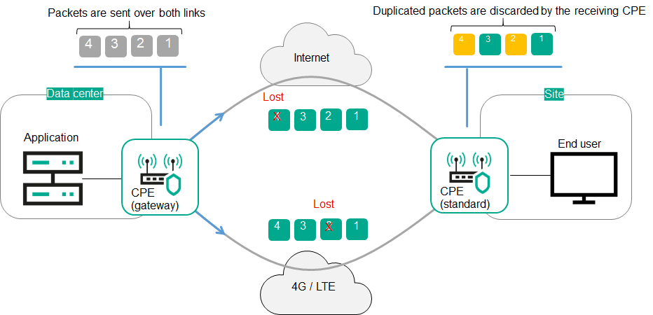
Duplication of traffic packets between CPE devices
Page topScenario: Directing application traffic to a transport service
The scenario for directing application traffic to a transport service involves the following steps:
- Creating a transport service
Create a transport service to which you want to direct application traffic. You can use the following instructions to complete this step:
- Creating a traffic classification rule
Create a traffic classification rule to identify the traffic of the application in the overall data stream. When creating a traffic classification rule, you must select the L3 protocol on the L3 fields tab, and select the application whose traffic you want to direct to the transport service on the DPI tab.
If you want to direct traffic of multiple applications to a transport service, you must create create a traffic classification rule for each application.
- Creating a traffic filter
Create a traffic filter to determine if routing the application traffic is allowed. When creating a traffic filter, you must add the traffic classification rules that you created for the application traffic to the traffic filter.
- Creating an ACL interface
Create an ACL interface to apply the traffic filter to traffic that is transmitted through this ACL interface. When creating an ACL interface, you must select a traffic filter that you created for the application traffic.
- Adding the ACL interface to the transport service
Edit the transport service to add the ACL interface that you created for the application traffic. You can use the following instructions to complete this step:
Application traffic is directed to the transport service.
Page topManaging Point-to-Point (P2P) transport services
To display the table of P2P services, go to the Infrastructure menu section, click Management → Configuration menu next to the controller, and go to the P2P services section. Information about P2P services is displayed in the following columns of the table:
- Name is the name of the P2P service.
- Source contains information about the source service interface of the P2P service:
- Name and DPID of the CPE device on which the service interface was created
- The number of the OpenFlow port which the service interface is mapped to.
- Destination contains information about the destination service interface of the P2P service:
- Name and DPID of the CPE device on which the service interface was created
- The number of the OpenFlow port which the service interface is mapped to.
- QoS is the quality of service rule specified for the source service interface of the P2P service.
- Backup port contains information about the backup service interface of the P2P service:
- Name and DPID of the CPE device on which the service interface was created
- The number of the OpenFlow port which the service interface is mapped to.
- Status is the status of the P2P service:
- Up
- Down
The actions that you can perform with the table are described in the Managing solution component tables instructions.
Creating a P2P service
To create a P2P service:
- In the menu, go to the Infrastructure section.
This opens the resource management page. By default, the Network resources tab is selected, which displays the table of controllers.
- Click Management → Configuration menu next to the controller.
This opens the controller configuration menu. By default, you are taken to the Controller nodes section, which displays a table of controller nodes.
- Go to the P2P services section.
A table of P2P services is displayed.
- In the upper part of the page, click + P2P service.
- This opens a window; in that window, in the Name field, enter the name of the P2P service.
- In the Constraint drop-down list, select the created Manual-TE constraint or threshold constraint that you want to add to the P2P service.
- In the Balancing mode drop-down list, select the balancing mode for distributing traffic among the links:
- Per-flow means the traffic streams (5-Tuple) are distributed among the links in accordance with the link cost. Default value.
- Per-packet means the traffic packets are distributed among the links in accordance with the link cost.
- Broadcast means the traffic packets are duplicated and transmitted simultaneously through all links to avoid loss.
You can manually specify link cost.
- If necessary, in the Description field, enter a brief description of the P2P service.
- In the Switch and Port drop-down lists on the left, select the CPE device and the created service interface that you want to use as the source service interface of the P2P service.
- In the Switch and Port drop-down lists on the right, select the CPE device and the created service interface that you want to use as the destination service interface of the P2P service.
- If you want to display service interfaces that were added to transport services in the Port drop-down lists, select the Show used interfaces check box. This check box is cleared by default.
- If you want to swap the values selected in the Port drop-down lists, select the Switch interfaces check box. This check box is cleared by default.
- If you want to add a reserve service interface of the P2P service source through which traffic is transmitted if the primary service interface fails:
- Select the Use backup interface check box. This check box is cleared by default.
- In the Backup switch and Backup port drop-down lists, select the CPE device and the created service interface that you want to use as the reserve service interface.
- If you want to display service interfaces that were added to transport services in the Backup port drop-down list, select the Show used interfaces check box. This check box is cleared by default.
If the primary source service interface of the P2P service goes up again, the P2P service keeps using the backup source service interface.
- In the Inbound filter drop-down lists on the left and right, select the created traffic filter for the source and destination interfaces of the P2P service.
- In the QoS drop-down list, select the created quality of service rule for the service interface of the P2P service source.
- If you want to track the status of the source and destination service interfaces of the P2P service and when one of the interfaces goes down, automatically disable the other, select the Propagate interface status check box. This check box is cleared by default. This check box cannot be selected when the Use backup interface check box is selected.
When the service interface that was disabled first goes back online, the second service interface that was automatically disabled also resumes operation. This functionality works only on service interfaces with Access traffic classification. You can select the type of traffic classification when creating a service interface.
- Click Create.
The P2P service is created and displayed in the table.
Viewing statistics of a P2P service
To view the statistics of a P2P service:
- In the menu, go to the Infrastructure section.
This opens the resource management page. By default, the Network resources tab is selected, which displays the table of controllers.
- Click Management → Configuration menu next to the controller.
- Go to the P2P services section.
A table of P2P services is displayed.
- Click Management → Statistics next to the P2P service whose statistics you want to view.
This opens a window with statistics of the P2P service.
Page topViewing and configuring the display of a P2P service topology
To view and configure the display of a P2P service topology:
- In the menu, go to the Infrastructure section.
This opens the resource management page. By default, the Network resources tab is selected, which displays the table of controllers.
- Click Management → Configuration menu next to the controller.
This opens the controller configuration menu. By default, you are taken to the Controller nodes section, which displays a table of controller nodes.
- Go to the P2P services section.
A table of P2P services is displayed.
- Click Management → Service topology next to the P2P service whose topology you want to view.
This opens a window with the P2P service topology.
- If you need to move CPE devices, do one of the following:
- If you want to manually change the position of CPE devices, click Manual and adjust the position of CPE devices.
- If you want to automatically arrange CPE devices, click Automatically and select one of the following values from the displayed drop-down list:
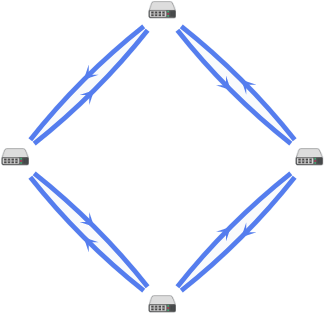
- Physical simulation — CPE devices are arranged approximately in accordance with their actual location relative to each other, for example:
- Random — The arrangement of CPE devices is randomized, for example:
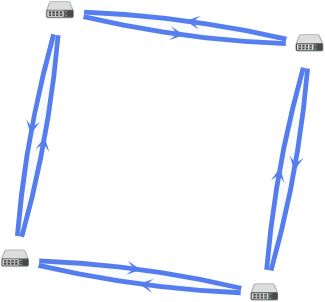
- Circle — CPE devices are arranged in accordance with a ring topology, for example:

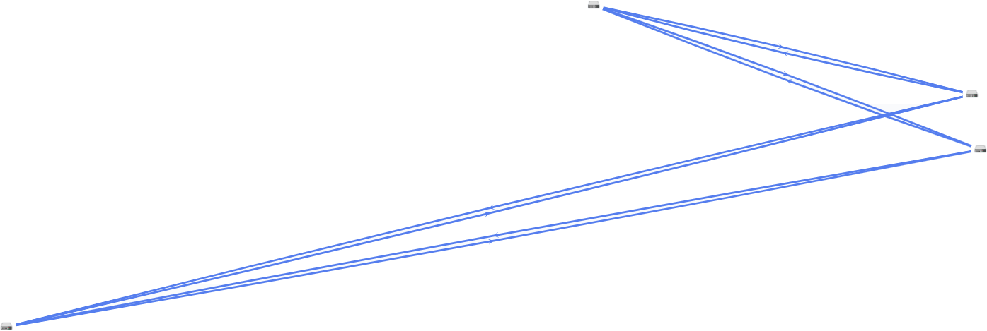
- Breadthfirst — CPE devices are arranged horizontally, for example:

- Concentric — CPE devices are arranged concentrically, for example:
- Grid — CPE devices are arranged in accordance with a grid topology, for example:

- Physical simulation — CPE devices are arranged approximately in accordance with their actual location relative to each other, for example:
- If you want to display information about CPE devices, select the following check boxes:
- Name displays the names of CPE devices.
- IP address displays the IP addresses of CPE devices.
These check boxes are cleared by default.
- If you want to display a segment between two CPE devices:
- Select the Segments check box. This check box is cleared by default.
- In the displayed drop-down lists, select the source and destination CPE devices of the segment.
The segment between the CPE devices is displayed.
Editing a P2P service
To edit a P2P service:
- In the menu, go to the Infrastructure section.
This opens the resource management page. By default, the Network resources tab is selected, which displays the table of controllers.
- Click Management → Configuration menu next to the controller.
This opens the controller configuration menu. By default, you are taken to the Controller nodes section, which displays a table of controller nodes.
- Go to the P2P services section.
A table of P2P services is displayed.
- Click Management → Edit next to the P2P service that you want to edit.
- This opens a window; in that window, if necessary, edit the P2P service settings. For a description of the settings, see the instructions for creating a P2P service.
- Click Save.
The P2P service is modified and updated in the table.
Restarting a P2P service
You can restart a P2P service to restore it in case of malfunctions. When you restart a P2P service, the controller automatically deletes and re-creates the rules associated with this P2P service in the OpenFlow tables of CPE devices. This affects CPE devices whose service interfaces are added to the P2P service.
To restart a P2P service:
- In the menu, go to the Infrastructure section.
This opens the resource management page. By default, the Network resources tab is selected, which displays the table of controllers.
- Click Management → Configuration menu next to the controller.
- Go to the P2P services section.
A table of P2P services is displayed.
- Click Management → Reprovision next to the P2P service that you want to reprovision.
- In the confirmation window, click Reprovision.
The P2P service is restarted.
Page topDeleting a P2P service
Deleted P2P services cannot be restored
To delete a P2P service:
- In the menu, go to the Infrastructure section.
This opens the resource management page. By default, the Network resources tab is selected, which displays the table of controllers.
- Click Management → Configuration menu next to the controller.
- Go to the P2P services section.
A table of P2P services is displayed.
- Click Management → Delete next to the P2P service that you want to delete.
- To delete the service interfaces added to the P2P service, select the Delete associated service interfaces check box in the confirmation window. This check box is cleared by default.
- Click Delete.
The P2P service is deleted and is no longer displayed in the table.
Page topManaging Point-to-Multipoint (P2M) transport services
To display the table of P2M services, go to the Infrastructure menu section, click Management → Configuration menu next to the controller, and go to the P2M services section. Information about P2M services is displayed in the following columns of the table:
- Name is the name of the P2M service.
- Mode indicates whether a DFI (Default Forwarding Interface) is used in the P2M service, to which unknown unicast traffic is sent:
- Classic if you do not want to use DFI. Default value.
- DFI with FIB on root and leafs if you want to use DFI on the service interface with the root role.
- DFI with FIB on leaf if you want to use DFI on the service interface with the root role. Service interfaces with the leaf role must be created on the same CPE device. Backup service interfaces with the leaf role must be created on the same CPE device, which must be different from the CPE device on which the primary service interfaces are created.
- MAC age (sec.) is the time period in seconds during which entries are kept in the MAC table of the controller.
- MAC learn mode is the action applied to a series of frames when the first frame is sent to the controller to learn the source MAC address:
- Learn and flood means the controller remembers the MAC address of the source and checks for the presence of the destination MAC address in the MAC table. If the destination MAC address is not in the MAC table, the series of frames is sent to all service interfaces added to the P2M service, except for the service interface on which the series of frames originally arrived.
- Learn and drop means the controller remembers the MAC address of the source and checks for the presence of the destination MAC address in the MAC table. If the destination MAC address is not in the MAC table, the series of frames is dropped.
If the destination MAC address is present in the MAC table, the series of frames is sent to the destination service interface.
- MAC table size is the maximum number of entries in the MAC table on the controller.
- MAC table overload is the policy for processing new MAC addresses when the MAC table of the controller is full:
- Flood means traffic with destination MAC addresses that have not been learned is transmitted as BUM traffic (Broadcast, unknown-unicast, and multicast).
- Drop means that traffic with destination MAC addresses that have not been learned is dropped.
- Endpoints is the information about service interfaces that have been added to the P2M service:
- Names and DPIDs of the CPE devices on which the service interfaces were created
- Numbers of OpenFlow ports which the service interfaces are mapped to
- Roles of the service interfaces:
- Root means the service interface can send traffic to service interfaces with any role.
- Leaf means the service interface can send traffic only to service interfaces with the Root role.
- Status is the status of the P2M service:
- Up
- Down
- Description is a brief description of the P2M service.
The actions you can perform with the table are described in the Managing solution component tables instructions.
Creating a P2M service
To create a P2M service:
- In the menu, go to the Infrastructure section.
This opens the resource management page. By default, the Network resources tab is selected, which displays the table of controllers.
- Click Management → Configuration menu next to the controller.
This opens the controller configuration menu. By default, you are taken to the Controller nodes section, which displays a table of controller nodes.
- Go to the P2M services section.
A table of P2M services is displayed.
- In the upper part of the page, click + P2M service.
- This opens a window; in that window, in the Name field, enter the name of the P2M service.
- In the Constraint drop-down list, select the created Manual-TE constraint or threshold constraint that you want to add to the P2M service.
- In the Balancing mode drop-down list, select the balancing mode for distributing traffic among the links:
- Per-flow means the traffic streams (5-Tuple) are distributed among the links in accordance with the link cost. Default value.
- Per-packet means the traffic packets are distributed among the links in accordance with the link cost.
- Broadcast means the traffic packets are duplicated and transmitted simultaneously through all links to avoid loss.
You can manually specify link cost.
- In the MAC learn mode drop-down list, select the action that you want to apply to a series of frames when the first frame is sent to the controller to learn the source MAC address:
- Learn and flood means the controller remembers the MAC address of the source and checks for the presence of the destination MAC address in the MAC table. If the destination MAC address is not in the MAC table, the series of frames is sent to all service interfaces added to the P2M service, except for the service interface on which the series of frames originally arrived. Default value.
- Learn and drop means the controller remembers the MAC address of the source and checks for the presence of the destination MAC address in the MAC table. If the destination MAC address is not in the MAC table, the series of frames is dropped.
If the destination MAC address is present in the MAC table, the series of frames is sent to the destination service interface.
- In the MAC age (sec.) field, enter the time period in seconds during which entries are kept in the MAC table of the controller. Range of values: 10 to 65,535. Default value:
300. - In the MAC table overload drop-down list, select the policy for processing new MAC addresses when the MAC table of the controller is full:
- Flood means traffic with destination MAC addresses that have not been learned is transmitted as BUM traffic (Broadcast, unknown-unicast, and multicast). Default value.
- Drop means that traffic with destination MAC addresses that have not been learned is dropped.
- In the MAC table size field, enter the maximum number of entries in the MAC table on the controller. Range of values: 0 to 65,535.
0means the number of records in the MAC table of the controller is not limited. Default value:100. - In the Mode drop-down list, select whether the P2M service uses a DFI (Default Forwarding Interface), to which unknown unicast traffic is sent:
- Classic if you do not want to use DFI. Default value.
- DFI with FIB on root and leafs if you want to use DFI on the service interface with the root role.
- DFI with FIB on leaf if you want to use DFI on the service interface with the root role. Service interfaces with the leaf role must be created on the same CPE device. Backup service interfaces with the leaf role must be created on the same CPE device, which must be different from the CPE device on which the primary service interfaces are created.
- If necessary, in the Description field, enter a brief description of the P2M service.
- Click Next to proceed to the next group of settings.
- Add the service interface to the P2M service:
- In the Switch and Port drop-down lists on the right, select the CPE device and the created service interface that you want to add to the P2M service.
- If you want to display service interfaces that were added to transport services in the Port drop-down list, select the Show used interfaces check box. This check box is cleared by default.
- In the QoS drop-down list, select the created quality of service rule for the service interface.
- In the Inbound filter drop-down list, select the created traffic filter for the service interface.
- In the Role drop-down list, select the role of the service interface:
- Root means the service interface can send traffic to service interfaces with any role.
- Leaf means the service interface can send traffic only to service interfaces with the Root role.
- If you want to add a reserve service interface through which traffic is transmitted if the primary service interface fails:
- Select the Use backup interface check box. This check box is cleared by default.
- In the Backup switch and Backup port drop-down lists, select the CPE device and the created service interface that you want to use as the reserve service interface.
- If you want to display service interfaces that were added to transport services in the Backup port drop-down list, select the Show used interfaces check box. This check box is cleared by default.
If the primary service interface goes back online, the P2M service continues to use the backup service interface.
- If you want to assign the DFI role to the service interface, select the Default Forwarding Interface check box. This check box cannot be selected if in the Role drop-down list, you selected Leaf. This check box is cleared by default.
- Click + Add.
The service interface is added and displayed in the lower part of the window. You can add multiple service interfaces or delete a service interface. To delete a service interface, click Delete next to it.
- Click Next to proceed to the next group of settings.
- If you want to add multiple service interfaces to the P2M service at the same time:
- In the Group drop-down list, select the created OpenFlow port group that you want to add to the P2M service. When you save the settings of the P2M service, service interfaces are automatically created that are mapped to OpenFlow ports in the OpenFlow port group, and then these service interfaces are automatically added to the P2M service.
- In the QoS drop-down list, select the created quality of service rule for automatically created service interfaces mapped to OpenFlow ports.
- In the VLAN ID field, enter the outer VLAN tag value for automatically created service interfaces mapped to OpenFlow ports. Service interfaces with the VLAN traffic classification type can only be created automatically. The same outer VLAN tag is assigned to each service interface.
- In the Role drop-down list, select the role for automatically created service interfaces mapped to OpenFlow ports:
- Root means the service interface can send traffic to service interfaces with any role.
- Leaf means the service interface can send traffic only to service interfaces with the Root role.
- Click + Add.
The OpenFlow group is added and displayed in the lower part of the window. You can add multiple OpenFlow port groups or delete an OpenFlow port group. To delete a group of OpenFlow ports, click Delete next to it.
- Click Create.
The P2M service is created and displayed in the table.
Viewing statistics of a P2M service
To view the statistics of a P2M service:
- In the menu, go to the Infrastructure section.
This opens the resource management page. By default, the Network resources tab is selected, which displays the table of controllers.
- Click Management → Configuration menu next to the controller.
- Go to the P2M services section.
A table of P2M services is displayed.
- Click Management → Statistics next to the P2M service whose statistics you want to view.
This opens a window with statistics of the P2M service.
Page topViewing the MAC table of a P2M service
To view the MAC table of a P2M service:
- In the menu, go to the Infrastructure section.
This opens the resource management page. By default, the Network resources tab is selected, which displays the table of controllers.
- Click Management → Configuration menu next to the controller.
- Go to the P2M services section.
A table of P2M services is displayed.
- Click Management → MAC table next to the P2M service whose MAC table you want to view.
This opens a window with the MAC table of the P2M service.
- If you want to find a specific MAC address, enter it in the field and click Find by MAC.
- If you want to clear the MAC table, click Clear.
Viewing and configuring the display of a P2M service topology
To view and configure the display of a P2M service topology:
- In the menu, go to the Infrastructure section.
This opens the resource management page. By default, the Network resources tab is selected, which displays the table of controllers.
- Click Management → Configuration menu next to the controller.
This opens the controller configuration menu. By default, you are taken to the Controller nodes section, which displays a table of controller nodes.
- Go to the P2M services section.
A table of P2M services is displayed.
- Click Management → Service topology next to the P2M service whose topology you want to view.
This opens a window with the P2M service topology.
- If you need to move CPE devices, do one of the following:
- If you want to manually change the position of CPE devices, click Manual and adjust the position of CPE devices.
- If you want to automatically arrange CPE devices, click Automatically and select one of the following values from the displayed drop-down list:
- Physical simulation — CPE devices are arranged approximately in accordance with their actual location relative to each other, for example:
- Random — The arrangement of CPE devices is randomized, for example:
- Circle — CPE devices are arranged in accordance with a ring topology, for example:
- Breadthfirst — CPE devices are arranged horizontally, for example:
- Concentric — CPE devices are arranged concentrically, for example:
- Grid — CPE devices are arranged in accordance with a grid topology, for example:
- Physical simulation — CPE devices are arranged approximately in accordance with their actual location relative to each other, for example:
- If you want to display information about CPE devices, select the following check boxes:
- Name displays the names of CPE devices.
- IP address displays the IP addresses of CPE devices.
These check boxes are cleared by default.
- If you want to display a segment between two CPE devices:
- Select the Segments check box. This check box is cleared by default.
- In the displayed drop-down lists, select the source and destination CPE devices of the segment.
The segment between the CPE devices is displayed.
Editing a P2M service
To edit a P2M service:
- In the menu, go to the Infrastructure section.
This opens the resource management page. By default, the Network resources tab is selected, which displays the table of controllers.
- Click Management → Configuration menu next to the controller.
This opens the controller configuration menu. By default, you are taken to the Controller nodes section, which displays a table of controller nodes.
- Go to the P2M services section.
A table of P2M services is displayed.
- Click Management → Edit next to the P2M service that you want to edit.
- This opens a window; in that window, if necessary, edit the P2M service settings. For a description of the settings, see the instructions for creating a P2M service.
- Click Save.
The P2M service is modified and updated in the table.
Restarting a P2M service
You can restart a P2M service to restore it in case of malfunctions. When you restart a P2M service, the controller automatically deletes and re-creates the rules associated with this P2M service in the OpenFlow tables of CPE devices. This affects CPE devices whose service interfaces are added to the P2M service.
To restart a P2M service:
- In the menu, go to the Infrastructure section.
This opens the resource management page. By default, the Network resources tab is selected, which displays the table of controllers.
- Click Management → Configuration menu next to the controller.
- Go to the P2M services section.
A table of P2M services is displayed.
- Click Management → Reprovision next to the P2M service that you want to reprovision.
- In the confirmation window, click Confirm.
The P2M service is restarted.
Page topDeleting a P2M service
Deleted P2M services cannot be restored.
To delete a P2M service:
- In the menu, go to the Infrastructure section.
This opens the resource management page. By default, the Network resources tab is selected, which displays the table of controllers.
- Click Management → Configuration menu next to the controller.
- Go to the P2M services section.
A table of P2M services is displayed.
- Click Management → Delete next to the P2M service that you want to delete.
- If you want to delete the service interfaces added to the P2M service, select the Delete associated service interfaces check box in the confirmation window. This check box is cleared by default.
- Click Delete.
The P2M service is deleted and is no longer displayed in the table.
Page topManaging Multipoint-to-Multipoint (M2M) transport services
To display the table of M2M services, go to the Infrastructure menu section, click Management → Configuration menu next to the controller, and go to the M2M services section. Information about M2M services is displayed in the following columns of the table:
- Name is the name of the M2M service.
- MAC age (sec.) is the time period in seconds during which entries are kept in the MAC table of the controller.
- MAC learn mode is the action applied to a series of frames when the first frame is sent to the controller to learn the source MAC address:
- MAC table size is the maximum number of entries in the MAC table on the controller.
- MAC table overload is the policy for processing new MAC addresses when the MAC table of the controller is full:
- Flood means traffic with destination MAC addresses that have not been learned is transmitted as BUM traffic (Broadcast, unknown-unicast, and multicast). Default value.
- Drop means that traffic with destination MAC addresses that have not been learned is dropped.
- Endpoints is the information about service interfaces that have been added to the M2M service:
- Names and DPIDs of the CPE devices on which the service interfaces were created
- Numbers of OpenFlow ports which the service interfaces are mapped to
- Roles of the service interfaces.
- Status is the status of the M2M service:
- Up
- Down
- Description is a brief description of the M2M service.
The actions you can perform with the table are described in the Managing solution component tables instructions.
Creating an M2M service
To create an M2M service:
- In the menu, go to the Infrastructure section.
This opens the resource management page. By default, the Network resources tab is selected, which displays the table of controllers.
- Click Management → Configuration menu next to the controller.
This opens the controller configuration menu. By default, you are taken to the Controller nodes section, which displays a table of controller nodes.
- Go to the M2M services section.
A table of M2M services is displayed.
- In the upper part of the page, click + M2M service.
- This opens a window; in that window, in the Name field, enter the name of the M2M service.
- In the Constraint drop-down list, select the created Manual-TE constraint or threshold constraint that you want to add to the M2M service.
- In the Balancing mode drop-down list, select the balancing mode for balancing traffic across links:
- Per-flow means the traffic streams (5-Tuple) are distributed among the links in accordance with the link cost. Default value.
- Per-packet means the traffic packets are distributed among the links in accordance with the link cost.
- Broadcast means the traffic packets are duplicated and transmitted simultaneously through all links to avoid loss.
You can manually specify link cost.
- In the MAC learn mode drop-down list, select the action that you want to apply to a series of frames when the first frame is sent to the controller to learn the source MAC address:
- Learn and flood means the controller remembers the MAC address of the source and checks for the presence of the destination MAC address in the MAC table. If the destination MAC address is not in the MAC table, the series of frames is sent to all service interfaces added to the M2M service, except for the service interface on which the series of frames originally arrived. Default value.
- Learn and drop means the controller remembers the MAC address of the source and checks for the presence of the destination MAC address in the MAC table. If the destination MAC address is not in the MAC table, the series of frames is dropped.
If the destination MAC address is present in the MAC table, the series of frames is sent to the destination service interface.
- In the MAC age (sec.) field, enter the time period in seconds during which entries are kept in the MAC table of the controller. Range of values: 10 to 65,535. Default value:
300. - In the MAC table overload drop-down list, select the policy for processing new MAC addresses when the MAC table of the controller is full:
- Flood means traffic with destination MAC addresses that have not been learned is transmitted as BUM traffic (Broadcast, unknown-unicast, and multicast). Default value.
- Drop means that traffic with destination MAC addresses that have not been learned is dropped.
- In the MAC table size field, enter the maximum number of entries in the MAC table on the controller. Range of values: 0 to 65,535.
0means the number of records in the MAC table of the controller is not limited. Default value:100. - If necessary, in the Description field, enter a brief description of the M2M service.
- Click Next to proceed to the next group of settings.
- Add the service interface to the M2M service:
- In the Switch and Port drop-down lists on the right, select the CPE device and the created service interface that you want to add to the M2M service.
- If you want to display service interfaces that were added to transport services in the Port drop-down list, select the Show used interfaces check box. This check box is cleared by default.
- In the QoS drop-down list, select the created quality of service rule for the service interface.
- In the Inbound filter drop-down list, select the created traffic filter for the service interface.
- If you want to add a reserve service interface through which traffic is transmitted if the primary service interface fails:
- Select the Use backup interface check box. This check box is cleared by default.
- In the Backup switch and Backup port drop-down lists, select the CPE device and the created service interface that you want to use as the reserve service interface.
- If you want to display service interfaces that were added to transport services in the Backup port drop-down list, select the Show used interfaces check box. This check box is cleared by default.
If the primary service interface goes back online, the M2M service continues to use the backup service interface.
- Click + Add.
The service interface is added and displayed in the lower part of the window. You can add multiple service interfaces or delete a service interface. To delete a service interface, click Delete next to it.
- Click Next to proceed to the next group of settings.
- If you want to add multiple service interfaces to the M2M service at the same time:
- In the Group drop-down list, select the created OpenFlow port group that you want to add to the M2M service. When you save the settings of the M2M service, service interfaces are automatically created that are mapped to OpenFlow ports in the OpenFlow port group, and then these service interfaces are automatically added to the M2M service.
- In the QoS drop-down list, select the created quality of service rule for automatically created service interfaces mapped to OpenFlow ports.
- In the VLAN ID field, enter the outer VLAN tag value for automatically created service interfaces mapped to OpenFlow ports. Service interfaces with the VLAN classification type can only be created automatically. The same outer VLAN tag is assigned to each service interface.
- Click + Add.
The OpenFlow group is added and displayed in the lower part of the window. You can add multiple OpenFlow port groups or delete an OpenFlow port group. To delete a group of OpenFlow ports, click Delete next to it.
- Click Create.
The M2M service is created and displayed in the table.
Viewing statistics of an M2M service
To view the statistics of an M2M service:
- In the menu, go to the Infrastructure section.
This opens the resource management page. By default, the Network resources tab is selected, which displays the table of controllers.
- Click Management → Configuration menu next to the controller.
- Go to the M2M services section.
A table of M2M services is displayed.
- Click Management → Statistics next to the M2M service whose statistics you want to view.
This opens a window with statistics of the M2M service.
Page topViewing the MAC table of an M2M service
To view the MAC table of an M2M service:
- In the menu, go to the Infrastructure section.
This opens the resource management page. By default, the Network resources tab is selected, which displays the table of controllers.
- Click Management → Configuration menu next to the controller.
- Go to the M2M services section.
A table of M2M services is displayed.
- Click Management → MAC table next to the M2M service whose MAC table you want to view.
This opens a window with the MAC table of the M2M service.
- If you want to find a specific MAC address, enter it in the field and click Find by MAC.
- If you want to clear the MAC table, click Clear.
Viewing and configuring the display of an M2M service topology
To view and configure the display of an M2M service topology:
- In the menu, go to the Infrastructure section.
This opens the resource management page. By default, the Network resources tab is selected, which displays the table of controllers.
- Click Management → Configuration menu next to the controller.
This opens the controller configuration menu. By default, you are taken to the Controller nodes section, which displays a table of controller nodes.
- Go to the M2M services section.
A table of M2M services is displayed.
- Click Management → Service topology next to the M2M service whose topology you want to view.
This opens a window with the M2M service topology.
- If you need to move CPE devices, do one of the following:
- If you want to manually change the position of CPE devices, click Manual and adjust the position of CPE devices.
- If you want to automatically arrange CPE devices, click Automatically and select one of the following values from the displayed drop-down list:
- Physical simulation — CPE devices are arranged approximately in accordance with their actual location relative to each other, for example:
- Random — The arrangement of CPE devices is randomized, for example:
- Circle — CPE devices are arranged in accordance with a ring topology, for example:
- Breadthfirst — CPE devices are arranged horizontally, for example:
- Concentric — CPE devices are arranged concentrically, for example:
- Grid — CPE devices are arranged in accordance with a grid topology, for example:
- Physical simulation — CPE devices are arranged approximately in accordance with their actual location relative to each other, for example:
- If you want to display information about CPE devices, select the following check boxes:
- Name displays the names of CPE devices.
- IP address displays the IP addresses of CPE devices.
These check boxes are cleared by default.
- If you want to display a segment between two CPE devices:
- Select the Segments check box. This check box is cleared by default.
- In the displayed drop-down lists, select the source and destination CPE devices of the segment.
The segment between the CPE devices is displayed.
Editing an M2M service
To edit an M2M service:
- In the menu, go to the Infrastructure section.
This opens the resource management page. By default, the Network resources tab is selected, which displays the table of controllers.
- Click Management → Configuration menu next to the controller.
This opens the controller configuration menu. By default, you are taken to the Controller nodes section, which displays a table of controller nodes.
- Go to the M2M services section.
A table of M2M services is displayed.
- Click Management → Edit next to the M2M service that you want to edit.
- This opens a window; in that window, if necessary, edit the M2M service settings. For a description of the settings, see the instructions for creating an M2M service.
- Click Save.
The M2M service is modified and updated in the table.
Restarting an M2M service
You can restart an M2M service to restore it in case of malfunctions. When you restart an M2M service, the controller automatically deletes and re-creates the rules associated with this M2M service in the OpenFlow tables of CPE devices. This affects CPE devices whose service interfaces are added to the M2M service.
To restart an M2M service:
- In the menu, go to the Infrastructure section.
This opens the resource management page. By default, the Network resources tab is selected, which displays the table of controllers.
- Click Management → Configuration menu next to the controller.
- Go to the M2M services section.
A table of M2M services is displayed.
- Click Management → Reprovision next to the M2M service that you want to reprovision.
- In the confirmation window, click Confirm.
The M2M service is restarted.
Page topDeleting an M2M service
Deleted M2M services cannot be restored.
To delete an M2M service:
- In the menu, go to the Infrastructure section.
This opens the resource management page. By default, the Network resources tab is selected, which displays the table of controllers.
- Click Management → Configuration menu next to the controller.
- Go to the M2M services section.
A table of M2M services is displayed.
- Click Management → Delete next to the M2M service that you want to delete.
- If you want to delete the service interfaces added to the M2M service, select the Delete associated service interfaces check box in the confirmation window. This check box is cleared by default.
- Click Delete.
The M2M service is deleted and is no longer displayed in the table.
Page topManaging L3 VPN transport services
To display the table of L3 VPN services, go to the Infrastructure menu section, click Management → Configuration menu next to the controller, and go to the L3 VPN services section. Information about L3 VPN services is displayed in the following columns of the table:
- Name is the of the L3 VPN service.
- Type is the topology type of the L3 VPN service.
- Inter-spoke through hub indicates whether communication is possible between spoke sites through the hub site:
- Yes
- No
- Endpoints is the information about the L3 interfaces that have been added to the L3 VPN service:
- If the L3 interfaces are mapped to M2M services, the M2M service names are displayed.
- If the L3 interfaces are mapped to service interfaces, the following information is displayed:
- Names and DPIDs of the CPE devices on which the service interfaces were created
- Numbers of OpenFlow ports which the service interfaces are mapped to
- Quality of service rules specified for the service interfaces
- Traffic filters specified for the service interfaces
- IP prefixes of the L3 interfaces
- MAC addresses of the L3 interfaces
- Time period in seconds during which entries are kept in the ARP table on the controller
- Routes is the information about static routes that have been added to the L3 VPN service:
- Destination IPv4 prefixes of static routes
- Gateway IPv4 addresses for routing traffic packets to destination IPv4 prefixes of static routes
- L3 interfaces behind which the destination IPv4 prefixes of static routes are
- Metrics of the static routes
- DHCP servers are IPv4 addresses of DHCP servers specified for the L3 VPN service.
- Status is the status of the L3 VPN service:
- Up
- Down
- Errors are errors that occurred while the L3 VPN service was running.
The actions you can perform with the table are described in the Managing solution component tables instructions.
Creating an L3 VPN service
To create an L3 VPN service:
- In the menu, go to the Infrastructure section.
This opens the resource management page. By default, the Network resources tab is selected, which displays the table of controllers.
- Click Management → Configuration menu next to the controller.
This opens the controller configuration menu. By default, you are taken to the Controller nodes section, which displays a table of controller nodes.
- Go to the L3 VPN services section.
A table of L3 VPN services is displayed.
- In the upper part of the page, click + L3 VPN service.
- This opens a window; in that window, in the Name field, enter the name of the L3 VPN service.
- In the Constraint drop-down list, select the created Manual-TE constraint or threshold constraint that you want to add to the L3 VPN service.
- In the Balancing mode drop-down list, select the balancing mode for balancing traffic across links:
- Per-flow means the traffic streams (5-Tuple) are distributed among the links in accordance with the link cost. Default value.
- Per-packet means the traffic packets are distributed among the links in accordance with the link cost.
- Broadcast means the traffic packets are duplicated and transmitted simultaneously through all links to avoid loss.
You can manually specify link cost.
- Click Next to proceed to the next group of settings.
- Add the L3 interface to the L3 VPN service:
- In the Mode drop-down list, select the type of the L3 interface:
- M2M service means the L3 interface is mapped to an M2M service.
- Service interface means the L3 interface is mapped to a service interface.
- If in the Mode drop-down list, you selected M2M service, in the M2M service drop-down list, select the created M2M service mapped to the L3 interface.
- If in the Mode drop-down list, you selectedService interface, configure the service interface:
- In the Switch and Port drop-down lists, select the CPE device and the created service interface to which the L3 interface is mapped.
- In the QoS drop-down list, select the created quality of service rule for the L3 interface.
- In the Inbound filter drop-down list, select the created traffic filter for the L3 interface.
- If you want to display service interfaces that were added to transport services in the Port drop-down list, select the Show used interfaces check box. This check box is cleared by default.
- In the IP field, enter the IP address of the L3 interface.
- In the Prefix length field, enter the length of the L3 interface prefix. Range of values: 0 to 32.
- In the MAC address field, enter the MAC address of the L3 interface. You can generate a MAC address by clicking Generate.
- In the ARP age (sec.) field, enter the time period in seconds during which entries are kept in the ARP table on the L3 VPN service. Range of values: 1 to 65,535. Default value:
200. - Click + Add.
The L3 interface is added and displayed in the lower part of the window. You can add multiple L3 interfaces or delete an L3 interface. To delete an L3 interface, click Delete next to it.
- In the Mode drop-down list, select the type of the L3 interface:
- Click Next to proceed to the next group of settings.
- If you want to add a static route to the L3 VPN service:
- In the IP field, enter the destination IPv4 address of the static route.
- In the Prefix length field, enter the length of the IPv4 prefix of the static route. Range of values: 0 to 32.
- In the SVI drop-down list, select the added L3 interface followed by the IPv4 prefix of the static route destination. You added an L3 interface at step 9 of these instructions.
- In the Gateway field, enter the IPv4 address of the gateway for routing traffic packets to the IPv4 prefix of the static route destination.
- In the Metric field, enter a metric for the static route. Default value:
0. - Click + Add.
The static route is added and displayed in the lower part of the window. You can add multiple static routes or delete a static route. To delete a static route, click Delete next to it.
- Click Next to proceed to the next group of settings.
- Click Create.
The L3 VPN service is created and displayed in the table.
Managing the ARP table of an L3 VPN service
To display the ARP table of the L3 VPN service, go to the Infrastructure section, click Management → Configuration menu next to the controller, go to the L3 VPN services section, and click Management → ARP table next to the L3 VPN service. Information about records is displayed in the following columns of the table:
- IP is the IP address of the service interface.
- MAC is the MAC address of the service interface.
- Service interface is the information about the service interface:
- Name and DPID of the CPE device on which the service interface was created
- Number of the OpenFlow port which the service interface is mapped to
- Timeout maximum life (sec.) is the time in seconds that has elapsed since the record was created.
The actions you can perform with the table are described in the Managing solution component tables instructions.
Creating a static record in the ARP table of an L3 VPN service
To create a static record in the ARP table of an L3 VPN service:
- In the menu, go to the Infrastructure section.
This opens the resource management page. By default, the Network resources tab is selected, which displays the table of controllers.
- Click Management → Configuration menu next to the controller.
- Go to the L3 VPN services section.
A table of L3 VPN services is displayed.
- Click Management → ARP table next to the L3 VPN service in whose ARP table you want to create a static record.
The page with the ARP table of the L3 VPN service is displayed.
- In the upper part of the page, click + Static ARP record.
- This opens a window; in that window, in the Switch and Port drop-down lists, select the CPE device and the created service interface for which you want to specify an IP address and a MAC address.
- In the IP address field, enter the IP address of the service interface.
- In the MAC field, enter the MAC address of the service interface.
- Click Create.
The static record is created and displayed in the ARP table of the L3 VPN service.
Page topEditing a static record in the ARP table of an L3 VPN service
To edit a static record in the ARP table of an L3 VPN service:
- In the menu, go to the Infrastructure section.
This opens the resource management page. By default, the Network resources tab is selected, which displays the table of controllers.
- Click Management → Configuration menu next to the controller.
- Go to the L3 VPN services section.
A table of L3 VPN services is displayed.
- Click Management → ARP table next to the L3 VPN service in whose ARP table you want to edit a static record.
The page with the ARP table of the L3 VPN service is displayed.
- Click Management → Edit next to the static record that you want to edit.
- This opens a window; in that window, if necessary, edit the IP address and/or MAC address of the service interface.
- Click Save.
The static record is modified and updated in the table.
Page topDeleting a static record in the ARP table of an L3 VPN service
Deleted static records in the ARP table of an L3 VPN service cannot be restored.
To delete a static record in the ARP table of an L3 VPN service:
- In the menu, go to the Infrastructure section.
This opens the resource management page. By default, the Network resources tab is selected, which displays the table of controllers.
- Click Management → Configuration menu next to the controller.
This opens the controller configuration menu. By default, you are taken to the Controller nodes section, which displays a table of controller nodes.
- Go to the L3 VPN services section.
A table of L3 VPN services is displayed.
- Click Management → ARP table next to the L3 VPN service in whose ARP table you want to delete a static record.
The page with the ARP table of the L3 VPN service is displayed.
- Click Management → Delete next to the static record that you want to delete.
- In the confirmation window, click Delete.
The static record is deleted and no longer displayed in the table.
Page topViewing the routing and forwarding table of an L3 VPN service
To view the routing and forwarding table of an L3 VPN service:
- In the menu, go to the Infrastructure section.
This opens the resource management page. By default, the Network resources tab is selected, which displays the table of controllers.
- Click Management → Configuration menu next to the controller.
- Go to the L3 VPN services section.
A table of L3 VPN services is displayed.
- Click Management → Routing table next to the L3 VPN service whose routing table you want to view.
This opens a window with the routing and forwarding table of the L3 VPN service.
Page topEditing an L3 VPN service
To edit an L3 VPN service:
- In the menu, go to the Infrastructure section.
This opens the resource management page. By default, the Network resources tab is selected, which displays the table of controllers.
- Click Management → Configuration menu next to the controller.
This opens the controller configuration menu. By default, you are taken to the Controller nodes section, which displays a table of controller nodes.
- Go to the L3 VPN services section.
A table of L3 VPN services is displayed.
- Click Management → Edit next to the L3 VPN service that you want to edit.
- This opens a window; in that window, if necessary, edit the L3 VPN service settings. For a description of the settings, see the instructions for creating an L3 VPN service.
- Click Save.
The L3 VPN service is modified and updated in the table.
Restarting an L3 VPN service
You can restart an L3 VPN service to restore it in case of malfunctions. When you restart an L3 VPN service, the controller automatically deletes and re-creates the rules associated with this L3 VPN service in the OpenFlow tables of CPE devices. This affects CPE devices whose service interfaces are added to the L3 VPN service.
To restart an L3 VPN service:
- In the menu, go to the Infrastructure section.
This opens the resource management page. By default, the Network resources tab is selected, which displays the table of controllers.
- Click Management → Configuration menu next to the controller.
- Go to the L3 VPN services section.
A table of L3 VPN services is displayed.
- Click Management → Reprovision next to the L3 VPN service that you want to reprovision.
- In the confirmation window, click Confirm.
The L3 VPN service is restarted.
Page topDeleting an L3 VPN service
Deleted L3 VPN services cannot be restored.
To delete an L3 VPN service:
- In the menu, go to the Infrastructure section.
This opens the resource management page. By default, the Network resources tab is selected, which displays the table of controllers.
- Click Management → Configuration menu next to the controller.
- Go to the L3 VPN services section.
A table of L3 VPN services is displayed.
- Click Management → Delete next to the L3 VPN service that you want to delete.
- If you want to delete the service interfaces added to the L3 VPN service, select the Delete associated service interfaces check box in the confirmation window. This check box is cleared by default.
- Click Delete.
The L3 VPN service is deleted and is no longer displayed in the table.
Page topManaging IP multicast transport services
To display the table of IP multicast services, go to the Infrastructure menu section, click Management → Configuration menu next to the controller, and go to the IP multicast services section. Information about IP multicast services is displayed in the following columns of the table:
- Name is the name of the IP multicast service.
- Source port contains information about the source service interface of the IP multicast service:
- Name and DPID of the CPE device on which the service interface was created
- The number of the OpenFlow port which the service interface is mapped to.
- Backup source port contains information about the backup source service interface of the IP multicast service:
- Name and DPID of the CPE device on which the service interface was created
- The number of the OpenFlow port which the service interface is mapped to.
- Querier IP is the IP address of the source service interface of the IP multicast service.
- Consumer ports contains information about the destination service interfaces of the IP multicast service:
- Names and DPIDs of the CPE devices on which the service interfaces were created
- Numbers of OpenFlow ports which the service interfaces are mapped to
- Groups contains information about multicast groups that have been added to the IP multicast service:
- IP addresses of multicast groups
- Prefix lengths of multicast groups
- Guaranteed bandwidth for multicast groups
- Status is the status of the IP multicast service:
- Up
- Down
- Errors are errors that occurred while the IP multicast service was running.
The actions you can perform with the table are described in the Managing solution component tables instructions.
Creating an IP multicast service
To create an IP multicast service:
- In the menu, go to the Infrastructure section.
This opens the resource management page. By default, the Network resources tab is selected, which displays the table of controllers.
- Click Management → Configuration menu next to the controller.
This opens the controller configuration menu. By default, you are taken to the Controller nodes section, which displays a table of controller nodes.
- Go to the IP multicast services section.
A table of IP multicast services is displayed.
- In the upper part of the page, click + IP multicast service.
- This opens a window; in that window, in the Name field, enter the name of the IP multicast service.
- In the Switch and Port drop-down lists, select the CPE device and the created service interface that you want to use as the source service interface of the IP multicast service.
- If you want to display service interfaces that were added to transport services in the Source port drop-down list, select the Show used interfaces check box. This check box is cleared by default.
- In the Querier IP field, enter the IP address of the source service interface of the IP multicast service.
- If you want to add a reserve service interface of the IP multicast service source through which traffic is transmitted if the primary service interface fails:
- Select the Use backup interface check box. This check box is cleared by default.
- In the Backup switch and Backup port drop-down lists, select the CPE device and the created service interface that you want to use as the reserve service interface.
- If you want to display service interfaces that were added to transport services in the Backup port drop-down list, select the Show used interfaces check box. This check box is cleared by default.
- If you want the IP multicast service to use the primary source service interface again when that service interface goes up again, select the Recovery auto-return check box. This check box is cleared by default.
- If you want the multicast traffic distribution tree to be built on the backup service interface, select the Backup multicast tree check box. As long as the primary service interface remains active, traffic packets on the backup service interface are dropped. This check box is selected by default.
- Select the IGMP proxy check box to use an IGMP proxy server. This allows you to maintain traffic transmission to active multicast groups to which at least one destination service interface of the IP multicast service is connected. This check box is cleared by default.
- In the QoS drop-down list, select the created quality of service rule for the service interface of the IP multicast service source.
- Click Next to proceed to the next group of settings.
- Add the destination service interface to the IP multicast service:
- In the Switch and Port drop-down lists, select the CPE device and the created service interface that you want to use as the destination service interface of the IP multicast service.
- If you want to display service interfaces that were added to transport services in the Port drop-down list, select the Show used interfaces check box. This check box is cleared by default.
- Click + Add.
The service interface is added and displayed in the lower part of the window. You can add multiple service interfaces or delete a service interface. To delete a service interface, click Delete next to it.
- Click Next to proceed to the next group of settings.
- Add the multicast group to the IP multicast service:
- In the IP address field, enter the IP address of the multicast group. Range of values: 224.0.0.0 to 239.255.255.255.
- In the Mask drop-down list, select the length of the multicast group prefix. Range of values: 24 to 32.
- In the GBR drop-down list, select the guaranteed bit rate (GBR) for the multicast group.
- Click + Add.
The multicast group is added and displayed in the lower part of the window. You can add multiple multicast groups or delete a multicast group. To delete a multicast group, click Delete next to it.
- Click Create.
The IP multicast service is created and displayed in the table.
Viewing statistics of an IP multicast service
To view the statistics of an IP multicast service:
- In the menu, go to the Infrastructure section.
This opens the resource management page. By default, the Network resources tab is selected, which displays the table of controllers.
- Click Management → Configuration menu next to the controller.
- Go to the IP multicast services section.
A table of IP multicast services is displayed.
- Click Management → Statistics next to the IP multicast service whose statistics you want to view.
This opens a window with statistics of the IP multicast service.
Page topEditing an IP multicast service
To edit an IP multicast service:
- In the menu, go to the Infrastructure section.
This opens the resource management page. By default, the Network resources tab is selected, which displays the table of controllers.
- Click Management → Configuration menu next to the controller.
This opens the controller configuration menu. By default, you are taken to the Controller nodes section, which displays a table of controller nodes.
- Go to the IP multicast services section.
A table of IP multicast services is displayed.
- Click Management → Edit source interfaces, Edit consumer interfaces, or Edit multicast groups next to the IP multicast service that you want to edit.
- This opens a window; in that window, if necessary, edit the IP multicast service settings. For a description of the settings, see the instructions for creating an IP multicast service.
- Click Save.
The IP multicast service is modified and updated in the table.
Deleting an IP multicast service
Deleted IP multicast services cannot be restored.
To delete an IP multicast service:
- In the menu, go to the Infrastructure section.
This opens the resource management page. By default, the Network resources tab is selected, which displays the table of controllers.
- Click Management → Configuration menu next to the controller.
- Go to the IP multicast services section.
A table of IP multicast services is displayed.
- Click Management → Delete next to the IP multicast service that you want to delete.
- If you want to delete the service interfaces added to the IP multicast service, select the Delete associated service interfaces check box in the confirmation window. This check box is cleared by default.
- Click Delete.
The IP multicast service is deleted and is no longer displayed in the table.
Page topManaging transport services in an SD-WAN instance template
To display the table of P2M services and M2M services in an SD-WAN instance template, go to the SD-WAN → SD-WAN instance templates section, click the SD-WAN instance template, and select the Transport services tab. Information about P2M services and M2M services is displayed in the following columns of the table:
- Name is the name of the P2M service or M2M service.
- Type is the type of transport service:
- P2M
- M2M
- Management tunnel indicates whether the P2M service or M2M service is a management service:
- Yes
- No
- Mode indicates whether a DFI (Default Forwarding Interface) is used in the P2M service, to which unknown unicast traffic is sent:
- Classic if you do not want to use DFI. Default value.
- DFI with FIB on root and leafs if you want to use DFI on the service interface with the root role.
- DFI with FIB on leaf if you want to use DFI on the service interface with the root role. Service interfaces with the leaf role must be created on the same CPE device. Backup service interfaces with the leaf role must be created on the same CPE device, which must be different from the CPE device on which the primary service interfaces are created.
The value in this column is displayed only if the value in the Type column is P2M.
- MAC age (sec.) is the time period in seconds during which entries are kept in the MAC table of the controller.
- MAC learn mode is the action applied to a series of frames when the first frame is sent to the controller to learn the source MAC address:
- Learn and flood means the controller remembers the MAC address of the source and checks for the presence of the destination MAC address in the MAC table. If the destination MAC address is not in the MAC table, the series of frames is sent to all service interfaces added to the M2M service, except for the service interface on which the series of frames originally arrived.
- Learn and drop means the controller remembers the MAC address of the source and checks for the presence of the destination MAC address in the MAC table. If the destination MAC address is not in the MAC table, the series of frames is dropped.
If the destination MAC address is present in the MAC table, the series of frames is sent to the destination service interface.
- MAC table size is the maximum number of entries in the MAC table on the controller.
- MAC table overload is the policy for processing new MAC addresses when the MAC table of the controller is full:
- Flood means traffic with destination MAC addresses that have not been learned is transmitted as BUM traffic (Broadcast, unknown-unicast, and multicast). Default value.
- Drop means that traffic with destination MAC addresses that have not been learned is dropped.
To display a list of L3 VPN services, select the L3 services tab.
Creating a P2M service or an M2M service in an SD-WAN instance template
To create a P2M service or an M2M service in an SD-WAN instance template:
- In the menu, go to the SD-WAN → SD-WAN instance templates section.
A table of SD-WAN instance templates is displayed.
- Click the SD-WAN instance template in which you want to create a P2M service or an M2M service.
The settings area is displayed in the lower part of the page. You can expand the settings area to fill the entire page by clicking the expand icon
 . By default, the Information tab is selected, which displays the name of the SD-WAN instance template.
 - Select the Transport services tab.
The X2M services tab with the table of P2M services and M2M services is selected by default.
- Click + Transport service.
- This opens a window; in that window, in the Name field, enter the name of the P2M or M2M service.
- In the Type drop-down list, select the type of the transport service:
- P2M If you select this option in the Mode drop-down list, select whether the P2M service uses a DFI (Default Forwarding Interface), to which unknown unicast traffic is sent:
- Classic if you do not want to use DFI. Default value.
- DFI with FIB on root and leafs if you want to use DFI on the service interface with the root role.
- DFI with FIB on leaf if you want to use DFI on the service interface with the root role. Service interfaces with the leaf role must be created on the same CPE device. Backup service interfaces with the leaf role must be created on the same CPE device, which must be different from the CPE device on which the primary service interfaces are created.
- M2M
- P2M If you select this option in the Mode drop-down list, select whether the P2M service uses a DFI (Default Forwarding Interface), to which unknown unicast traffic is sent:
- If you want to make a P2M or M2M service the management service, select the Management tunnel check box. This check box is cleared by default. Only one transport service can be the management service.
- In the MAC learn mode drop-down list, select the action that you want to apply to a series of frames when the first frame is sent to the controller to learn the source MAC address:
- Learn and flood means the controller remembers the MAC address of the source and checks for the presence of the destination MAC address in the MAC table. If the destination MAC address is not in the MAC table, the series of frames is sent to all service interfaces added to the P2M service, except for the service interface on which the series of frames originally arrived. Default value.
- Learn and drop means the controller remembers the MAC address of the source and checks for the presence of the destination MAC address in the MAC table. If the destination MAC address is not in the MAC table, the series of frames is dropped.
If the destination MAC address is present in the MAC table, the series of frames is sent to the destination service interface.
- In the MAC table size field, enter the maximum number of entries in the MAC table on the controller. Range of values: 0 to 65,535.
0means the number of records in the MAC table of the controller is not limited. Default value:100. - In the MAC age (sec.) field, enter the time period in seconds during which entries are kept in the MAC table of the controller. Range of values: 10 to 65,535. Default value:
300. - In the MAC table overload drop-down list, select the policy for processing new MAC addresses when the MAC table of the controller is full:
- Flood means traffic with destination MAC addresses that have not been learned is transmitted as BUM traffic (Broadcast, unknown-unicast, and multicast). Default value.
- Drop means that traffic with destination MAC addresses that have not been learned is dropped.
- Click Create.
A P2M service or an M2M service is created and displayed in the table.
- In the upper part of the settings area, click Save to save the settings of the SD-WAN instance template.
Creating an L3 VPN service in an SD-WAN instance template
To create an L3 VPN service in an SD-WAN instance template:
- In the menu, go to the SD-WAN → SD-WAN instance templates section.
A table of SD-WAN instance templates is displayed.
- Click the SD-WAN instance template in which you want to create an L3 VPN service.
The settings area is displayed in the lower part of the page. You can expand the settings area to fill the entire page by clicking the expand icon
. By default, the Information tab is selected, which displays the name of the SD-WAN instance template. - Select the Transport services → L3 services tab.
A list of L3 VPN services is displayed.
- Click + Transport service.
- This opens a window; in that window, enter the name of the L3 VPN service.
- Click Create.
The L3 VPN service is created and displayed in the table.
- In the upper part of the settings area, click Save to save the settings of the SD-WAN instance template.
Editing a transport service in an SD-WAN instance template
To edit a transport service in an SD-WAN instance template:
- In the menu, go to the SD-WAN → SD-WAN instance templates section.
A table of SD-WAN instance templates is displayed.
- Click the SD-WAN instance template in which you want to edit a transport service.
The settings area is displayed in the lower part of the page. You can expand the settings area to fill the entire page by clicking the expand icon
. By default, the Information tab is selected, which displays the name of the SD-WAN instance template. - If you want to edit a P2M service or M2M service:
- Select the Transport services tab.
The X2M services tab with the table of P2M services and M2M services is selected by default.
- Click Edit next to the P2M service or M2M service that you want to edit.
- This opens a window; in that window, if necessary, edit the P2M service or M2M service settings. For a description of the settings, see the instructions for creating a P2M service or M2M service in an SD-WAN instance template.
- Select the Transport services tab.
- If you want to edit an L3 VPN service:
- Select the Transport services → L3 services tab.
A list of L3 VPN services is displayed.
- Click Edit next to the L3 VPN service that you want to edit.
- This opens a window; in that window, if necessary, edit the L3 VPN service name.
- Select the Transport services → L3 services tab.
- Click Save.
The transport service is modified and updated in the table.
- In the upper part of the settings area, click Save to save the settings of the SD-WAN instance template.
Deleting a transport service in an SD-WAN instance template
Transport services that are deleted in the SD-WAN instance template cannot be restored.
To delete a transport service in an SD-WAN instance template:
- In the menu, go to the SD-WAN → SD-WAN instance templates section.
A table of SD-WAN instance templates is displayed.
- Click the SD-WAN instance template in which you want to delete a transport service.
The settings area is displayed in the lower part of the page. You can expand the settings area to fill the entire page by clicking the expand icon
. By default, the Information tab is selected, which displays the name of the SD-WAN instance template. - If you want to delete a P2M service or M2M service:
- Select the Transport services tab.
The X2M services tab with the table of P2M services and M2M services is selected by default.
- Click Delete next to the P2M service or M2M service that you want to delete.
The P2M service or M2M service is deleted and no longer displayed in the table.
- Select the Transport services tab.
- If you want to delete an L3 VPN service:
- Select the Transport services → L3 services tab.
A list of L3 VPN services is displayed.
- Click Delete next to the L3 VPN service that you want to delete.
The L3 VPN service is deleted and is no longer displayed in the table.
- Select the Transport services → L3 services tab.
- In the upper part of the settings area, click Save to save the settings of the SD-WAN instance template.
Managing transport services in a CPE template
To display the table of transport services in a CPE template, go to the SD-WAN → CPE templates menu section, click the CPE template, and select the Transport services tab. Information about transport services is displayed in the following columns of the table:
- Name is the name of the transport service.
- QoS name is the name of the quality of service rule for the service interface, which is automatically created for connecting the CPE device to the transport service.
- Stage is the state in which the CPE device connects to the transport service:
- Before activation means that the CPE device connects to the transport service before this CPE device is enabled.
- After activation means that the CPE device connects to the transport service after this CPE device is enabled.
You can select which state the CPE device is in after registration when adding a CPE device.
- Type is the type of the transport service:
- P2M
- M2M
- L3 VPN
- Connection settings contains information about the service interface that is automatically created for connecting a CPE device to the transport service:
- Role of the service interface:
- Leaf
- Root
Displayed only if the value in the Type column is P2M.
- Traffic classification type on the service interface:
- Access
- VLAN
- Q-in-Q
- Outer VLAN tag of the service interface. Displayed only if the traffic classification type on the service interface is VLAN or Q-in-Q.
- Inner VLAN tag of the service interface. Displayed only if the traffic classification type on the service interface is Q-in-Q.
- Role of the service interface:
Adding a transport service to a CPE template
To add a transport service to a CPE template:
- In the menu, go to the SD-WAN → CPE templates subsection.
A table of CPE templates is displayed.
- Click the CPE template to which you want to add a transport service.
The settings area is displayed in the lower part of the page. You can expand the settings area to fill the entire page by clicking the expand icon
. By default, the Information tab is selected, which displays general information about the CPE template. - Select the Transport services tab.
A table of transport services is displayed.
- Click + Transport service.
- This opens a window; in that window, in the Name field, enter the name of the created transport service. If the actual name of the transport service does not match the name specified in the CPE template, the CPE device does not connect to the transport service.
- In the QoS name field, enter the name of the created quality of service rule for the service interface, which is automatically created for connecting the CPE device to the transport service. If the actual name of the quality of service rule does not match the name specified in the CPE template, the quality of service rule is not applied to the service interface.
- In the Stage drop-down list, select the state in which the CPE device connects to the transport service:
- Before activation means that the CPE device connects to the transport service before this CPE device is enabled.
- After activation means that the CPE device connects to the transport service after this CPE device is enabled.
You can select which state the CPE device is in after registration when adding or manually registering a CPE device.
- In the Type drop-down list, select the type of the transport service:
- P2M If you select this option in the Role drop-down list, select the role of the service interface that is automatically created for connecting the CPE device to the transport service:
- Leaf
- Root
- M2M
- L3 VPN If you select this option, do the following:
- In the IP address field, enter the IP address of the L3 interface.
- In the Mask field, enter the length of the L3 interface prefix. Range of values: 0 to 32.
If the actual type of the transport service does not match the type specified in the CPE template, the CPE device does not connect to the transport service.
- P2M If you select this option in the Role drop-down list, select the role of the service interface that is automatically created for connecting the CPE device to the transport service:
- In the Encapsulation drop-down list, select the traffic classification type on the service interface that is automatically created for connecting the CPE device to the transport service:
- Access Default value.
- VLAN If you select this option, in the VLAN ID field, enter the outer VLAN tag of the service interface. Range of values: 1 to 4094.
- Q-in-Q If you select this value, configure the L3 interface that is automatically created and mapped to the service interface:
- In the VLAN ID field, enter the outer VLAN tag of the service interface. Range of values: 1 to 4094.
- In the Inner VLAN ID field, enter the inner VLAN tag of the service interface. Range of values: 1 to 4094.
- Click Create.
The transport service is created and displayed in the table.
- In the upper part of the settings area, click Save to save CPE template settings.
Editing a transport service in a CPE template
To edit a transport service in a CPE template:
- In the menu, go to the SD-WAN → CPE templates subsection.
A table of CPE templates is displayed.
- Click the CPE template in which you want to edit a transport service.
The settings area is displayed in the lower part of the page. You can expand the settings area to fill the entire page by clicking the expand icon
. By default, the Information tab is selected, which displays general information about the CPE template. - Select the Transport services tab.
A table of transport services is displayed.
- Click Edit next to the transport service that you want to edit.
- This opens a window; in that window, if necessary, edit the transport service settings. For a description of the settings, see the instructions for adding a transport service to a CPE template.
- Click Save.
The transport service is modified and updated in the table.
- In the upper part of the settings area, click Save to save CPE template settings.
Deleting a transport service from a CPE template
Transport services that are deleted in the CPE template cannot be restored.
To delete a transport service in a CPE template:
- In the menu, go to the SD-WAN → CPE templates subsection.
A table of CPE templates is displayed.
- Click the CPE template in which you want to delete a transport service.
The settings area is displayed in the lower part of the page. You can expand the settings area to fill the entire page by clicking the expand icon
. By default, the Information tab is selected, which displays general information about the CPE template. - Select the Transport services tab.
A table of transport services is displayed.
- Click Delete next to the transport service that you want to delete.
The transport service is deleted and is no longer displayed in the table.
- In the upper part of the settings area, click Save to save CPE template settings.
Traffic mirroring and forwarding between CPE devices
Kaspersky SD-WAN supports traffic forwarding and mirroring between CPE devices. You can redirect or mirror traffic from traffic collection points to traffic destination using TAP services. Forwarding means sending traffic that arrives to traffic collection points to the traffic destination point, and mirroring means sending a copy of the traffic.
Service interfaces are used as collection points and destinations of traffic. Both individual service interfaces and service interfaces added to a transport service can be traffic collection points.
You need to create a traffic destination and then specify this traffic destination and traffic collection points when creating or editing a TAP service. You do not need to create traffic collection points in advance.
Managing traffic destinations
To display the list of traffic destinations, go to the Infrastructure menu section, click Management → Configuration menu next to the controller, and go to the TAP services section.
The actions you can perform with the list are described in the Managing solution component tables instructions.
Creating a traffic destination
To create a traffic destination:
- In the menu, go to the Infrastructure section.
This opens the resource management page. By default, the Network resources tab is selected, which displays the table of controllers.
- Click Management → Configuration menu next to the controller.
- Go to the TAP services section.
By default, the Mirroring destinations tab is selected, which displays the table of traffic destinations.
- In the upper part of the page, click + Mirroring destination.
- This opens a window; in that window, in the Switch and Port drop-down lists, select the CPE device and the created service interface that you want to use as the traffic destination.
- Click Create.
The traffic destination is created and displayed in the table.
Page topDeleting a traffic destination
Deleted traffic destinations cannot be restored.
To delete a traffic destination:
- In the menu, go to the Infrastructure section.
This opens the resource management page. By default, the Network resources tab is selected, which displays the table of controllers.
- Click Management → Configuration menu next to the controller.
- Go to the TAP services section.
By default, the Mirroring destinations tab is selected, which displays the table of traffic destinations.
- Click Delete next to the traffic destination that you want to delete.
- In the confirmation window, click Delete.
The traffic destination is deleted and is no longer displayed in the table.
Page topManaging TAP services
To display the table of TAP services, go to the Infrastructure menu section, click Management → Configuration menu next to the controller, go to the TAP services section, and select the TAP services tab. Information about TAP services is displayed in the following columns of the table:
- Mirroring destination contains information about the service interface used as the traffic destination:
- Name and DPID of the CPE device on which the service interface was created
- Number of the OpenFlow port which the service interface is mapped to
- Mirror traffic indicates whether the TAP service mirrors traffic from traffic collection points to the traffic destination:
- Yes
- No
- Type is the type of traffic collection points:
- SI means individual service interfaces are used as traffic collection points.
- If the service interfaces used as traffic collection points are added to a transport service, the type of the transport service is displayed:
- P2P
- IP multicast
- L3 VPN
- P2M
- M2M
- Transport service is the transport service to which the service interfaces being used as traffic collection points have been added. The value in this column is displayed only if the Source point type column is displaying the type of the transport service.
- Source points contains information about service interfaces that are being used as traffic collection points:
- Names and DPIDs of the CPE devices on which the service interfaces were created
- Numbers of OpenFlow ports which the service interfaces are mapped to
- Status is the status of the TAP service:
- Up
- Down
The actions you can perform with the table are described in the Managing solution component tables instructions.
Creating a TAP service
To create a TAP service:
- In the menu, go to the Infrastructure section.
This opens the resource management page. By default, the Network resources tab is selected, which displays the table of controllers.
- Click Management → Configuration menu next to the controller.
This opens the controller configuration menu. By default, you are taken to the Controller nodes section, which displays a table of controller nodes.
- Go to the TAP services section.
By default, the Mirroring destinations tab is selected, which displays the table of traffic destinations.
- Select the TAP services tab.
A table of TAP services is displayed.
- In the upper part of the page, click + TAP service.
- If you want the TAP service to mirror traffic from traffic collection points to the traffic destination, select the Mirror traffic check box. When this check box is selected, a copy of the traffic is sent to the destination; when the check box is cleared, the traffic is forwarded. This check box is cleared by default.
- In the Balancing mode drop-down list, select the balancing mode for balancing traffic across links:
- Per-flow means the traffic streams (5-Tuple) are distributed among the links in accordance with the link cost. Default value.
- Per-packet means the traffic packets are distributed among the links in accordance with the link cost.
- Broadcast means the traffic packets are duplicated and transmitted simultaneously through all links to avoid loss.
You can manually specify link cost.
- In the Mirroring destination drop-down list, select the created traffic destination.
- In the Source point type drop-down list, select the traffic collection point type:
- Service interface means individual service interfaces are used as traffic collection points.
- Transport service means service interfaces that are added to a transport service are used as traffic collection points.
- If in the Source point type drop-down list, you selected Transport service, follow these steps:
- In the Type drop-down list, select the type of the transport service:
- P2P
- IP multicast
- L3 VPN
- P2M
- M2M
- In the Transport service drop-down list, select the transport service.
- In the Type drop-down list, select the type of the transport service:
- In the Source points drop-down list, select the created service interface that you want to use as a traffic collection point.
The traffic collection point is added and displayed in the lower part of the window. You can add multiple traffic collection points or delete a traffic collection point. To delete a traffic collection point, click Delete next to it.
- Click Next and select the created traffic classification rules for traffic collection points.
- Click Create.
The TAP service is created and displayed in the table.
Page topViewing statistics of a TAP service
To view the statistics of a TAP service:
- In the menu, go to the Infrastructure section.
This opens the resource management page. By default, the Network resources tab is selected, which displays the table of controllers.
- Click Management → Configuration menu next to the controller.
- Go to the TAP services section.
By default, the Mirroring destinations tab is selected, which displays the table of traffic destinations.
- Select the TAP services tab.
A table of TAP services is displayed.
- Click Management → Statistics next to the TAP service whose statistics you want to view.
This opens a window with statistics of the TAP service.
Page topEditing a TAP service
To edit a TAP service:
- In the menu, go to the Infrastructure section.
This opens the resource management page. By default, the Network resources tab is selected, which displays the table of controllers.
- Click Management → Configuration menu next to the controller.
- Go to the TAP services section.
By default, the Mirroring destinations tab is selected, which displays the table of traffic destinations.
- Select the TAP services tab.
A table of TAP services is displayed.
- Click Management → Edit next to the TAP service that you want to edit.
- This opens a window; in that window, edit the TAP service settings, if necessary. For a description of the settings, see the instructions for creating a TAP service.
- Click Save.
The TAP service is modified and updated in the table.
Page topDeleting a TAP service
Deleted TAP services cannot be restored.
To delete a TAP service:
- In the menu, go to the Infrastructure section.
This opens the resource management page. By default, the Network resources tab is selected, which displays the table of controllers.
- Click Management → Configuration menu next to the controller.
- Go to the TAP services section.
By default, the Mirroring destinations tab is selected, which displays the table of traffic destinations.
- Select the TAP services tab.
A table of TAP services is displayed.
- Click Management → Delete next to the TAP service that you want to delete.
- To delete the service interfaces added to the TAP service, select the Delete associated service interfaces check box in the confirmation window. This check box is cleared by default.
- Click Delete.
The TAP service is deleted and is no longer displayed in the table.
Page top