Contents
- Managing CPE devices
- About the interaction of the CPE device and the orchestrator
- About the interaction of the CPE device and the controller
- Default credentials of KESR CPE devices
- Scenario: Automatic registration (ZTP) of a CPE device
- Scenario: Deployment on the VMware virtualization platform and automatic registration (ZTP) of a vCPE device
- Scenario: Re-registering a CPE device
- Managing CPE templates
- Managing CPE devices
- Adding a CPE device
- Generating an URL with basic CPE device settings
- Manually registering a CPE device
- Unregistering a CPE device
- Specifying the address of a CPE device
- Enabling and disabling a CPE device
- Restarting a CPE device
- Shutting down a CPE device
- Connecting to the CPE device console
- Viewing the password of a CPE device
- Exporting orchestrator and controller connection settings and SD-WAN interfaces from a CPE device
- Exporting network interfaces from a CPE device
- Changing the DPID of a CPE device
- Deleting CPE devices
- Two-factor authentication of a CPE device
- Managing certificates
- Automatically deleting and disabling CPE devices
- Grouping CPE devices using tags
- Configuring logs on CPE devices
- Specifying NTP servers on CPE devices
- Managing modems
- Updating firmware
- Manually updating firmware on a CPE device
- Uploading firmware to the orchestrator web interface
- Scheduling firmware updates on selected CPE devices
- Scheduling firmware updates on CPE devices with specific tags
- Restoring firmware of a KESR-M1 CPE device
- Restoring firmware of a KESR-M2-5 CPE device
- Correspondence of CPE device models with firmware versions
- Deleting firmware
- Additional configuration of CPE devices using scripts
- Managing network interfaces
- Creating network interfaces
- Creating a network interface with automatic assignment of an IP address via DHCP
- Creating a network interface with a static IPv4 address
- Creating a network interface with a static IPv6 address
- Creating a network interface for connecting to an LTE network
- Creating a network interface for connecting to a PPPoE server
- Creating a network interface without an IP address
- Editing a network interface
- Disabling or enabling a network interface
- Canceling the application of network interface settings to a CPE device
- Deleting a network interface
- Creating network interfaces
- Configuring the connection of a CPE device to the orchestrator and controller
- Managing SD-WAN interfaces
- About sending information about SD-WAN interfaces of the WAN type to the controller
- Package fragmentation
- Traffic queues on SD-WAN interfaces
- Creating an SD-WAN interface of the WAN type
- Editing an SD-WAN interface
- Disabling or enabling an SD-WAN interface
- Deleting an SD-WAN interface of the WAN type
- Managing service interfaces
- Managing OpenFlow port groups
- Configuring a UNI for connecting CPE devices to network services
- Adding a static route
- Filtering routes and traffic packets
- Route exchange over BGP
- Route exchange over OSPF
- Using BFD to detect routing failures
- Ensuring high availability with VRRP
- Transmission of multicast traffic using PIM and IGMP protocols
- Managing virtual routing and forwarding (VRF) tables
- Monitoring traffic packet information using the NetFlow protocol
- Diagnosing a CPE device
- Running scheduled tasks on CPE devices
Managing CPE devices
relay traffic between your organization's locations and clients, and also have direct access to the internet (DIA) without relaying traffic to the central office. For building the SD-WAN network, an OpenFlow virtual switch (virtual switch; vSwitch) is installed on CPE devices. You can use CPE devices of the following types:- CPE devices of the KESR model purchased from Kaspersky.
- Virtual CPE devices (vCPE devices) deployed on virtual machines. When using vCPE devices, you must make sure that the virtual machines satisfy the hardware and software requirements.
- Universal CPE devices (uCPE devices) which support VIM and virtual network function deployment.
For centralized configuration of CPE devices, you can use CPE templates. To avoid configuring each CPE device individually, you can specify the settings in the CPE template and then apply the template to CPE devices when adding or manually registering them. If you edit a setting in a CPE template, the setting is automatically modified on all CPE devices that are using this CPE template. If you edit a setting on the CPE device, the setting becomes independent of the CPE template, and if the setting is modified in the CPE template, it remains unchanged on the CPE device.
Certain CPE device settings can only be specified in a CPE template, for example, the port number for connecting to the orchestrator.
New CPE devices are registered automatically using Zero Touch Provisioning (ZTP). You add the CPE device in the orchestrator web interface, generate a URL with basic settings, and enter that URL on the CPE device. When the CPE device connects to the orchestrator using the received basic settings, it is mapped to the added record and is automatically registered. Registration does not require connecting to Kaspersky cloud services.
You can use two-factor authentication to register the CPE device securely. Two-factor authentication records a token (security key) to the orchestrator database; the token is then placed on the CPE device using the URL with basic settings. Registration succeeds if, when the CPE device connects to the orchestrator, the token placed on the device matches the CPE token in the orchestrator database.
When you remove a CPE device from the orchestrator web interface, the basic settings are retained on the CPE device. If you need to register the device again, you must restart the CPE device to make it connect to the orchestrator, and when it appears in the orchestrator web interface, you must manually register the CPE device. You cannot use two-factor authentication when re-registering a CPE device.
When adding and registering a CPE device, you can select if you want it to be automatically enabled after registration. When a CPE device is enabled, the CPE template is applied to it and the CPE device becomes available for relaying traffic.
About the interaction of the CPE device and the orchestrator
After registration, the CPE device sends REST API requests to the orchestrator to receive tasks not related to virtual switch management, such as restarting the CPE device and updating firmware. Requests are sent periodically with a frequency that you can specify when configuring the connection of the CPE device to the orchestrator and controller.
To display the table of tasks performed by the orchestrator on a CPE device, go to the SD-WAN → CPE menu section and click the CPE device. Information about tasks is displayed in the following columns of the table:
- Type is the type of the task.
- Status is the status of the task:
- Await means the task is saved in the orchestrator database and is waiting to be received by the CPE device.
- Executing means the task is running.
- Completed means the task is successfully completed.
- Error means an error occurred while running the task.
- Last update is the date and time of the last update of the task.
The orchestrator runs tasks on the CPE device in the following way:
- You run a task, such as modifying BGP settings, on the CPE device using the orchestrator web interface.
- The orchestrator saves the task in the database. In the table, the task is displayed with the Await status.
- The CPE device receives the task when it sends a REST API request to the orchestrator. In the table, the task is displayed with the Executing status.
- If the task finishes successfully, the CPE device reports this to the orchestrator. In the table, the task is displayed with the Completed status.
- If the task fails, it is displayed in the table with the Error status.
Before running the task, the current settings on the CPE device are saved. If the CPE device cannot send a confirmation message to the orchestrator after successful completion of the task, after 3 attempts the previous settings are restored on the CPE device, and the table displays the task with the Error status.
About the interaction of the CPE device and the controller
After the CPE device is registered, management sessions are established between its SD-WAN interfaces of the WAN type and the TCP ports of controller nodes. One of the management sessions is the primary session, and the others are in standby mode. The main management session is used to transmit tasks related to managing the virtual switch of the CPE device, such as modifying path settings. If the primary management session is terminated, a new primary management session is chosen randomly from previously established management sessions.
Management sessions are established by matching OpenFlow port numbers referenced by SD-WAN interfaces of the WAN type to TCP port numbers of the controller nodes, based on their order. For example, in the figure below, the CPE device has four SD-WAN interfaces that reference OpenFlow ports 4800, 4801, 4802, and 4803. The controller nodes have TCP ports 6653, 6654, 6655, 6656. In this case, management sessions are established as follows:
- SD-WAN 4800 → 6653
- SD-WAN 4801 → 6654
- SD-WAN 4802 → 6655
- SD-WAN 4803 → 6656
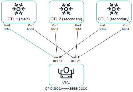
Management sessions between a CPE device and three controller nodes
Management sessions can be configured while configuring the connection of the CPE device to the orchestrator and controller. For example, you can select an SD-WAN interface of the WAN type to prioritize it for the purposes of establishing the primary management session; you can also enable or disable encryption for management sessions.
You can change the IP addresses and TCP port numbers of the controller nodes while configuring the controller nodes of an SD-WAN instance. This automatically changes the IP addresses and TCP port numbers of controller nodes on all CPE devices that are added to the SD-WAN instance. If SD-WAN interfaces of the WAN type of the CPE device are connected to different networks, for example, the internet and a private MPLS network, you can change the IP addresses and TCP port numbers of controller nodes on individual SD-WAN interfaces of the WAN type when you create or edit SD-WAN interfaces of the WAN type. The IP addresses and TCP port numbers specified on the SD-WAN interface of the WAN type take precedence over the IP addresses and TCP port numbers specified when configuring the controller nodes of the SD-WAN instance.
To display the table of CPE devices with information about management sessions, go to the Infrastructure menu section, click Management → Configuration menu next to the controller, and go to the Switches section. Information about management sessions is displayed in the following table columns:
- Name is the name of the CPE device.
- ID is the sequence number of the CPE device. The CPE device with the lowest sequence number was the first to connect to the controller.
- Status is the status of the CPE device in relation to the controller:
- Active means the CPE device can be used to relay traffic.
- Inactive means the CPE device cannot be used to relay traffic.
- Connection is the status of the CPE device connection to the controller:
- Connected means management sessions are established between the CPE device and the controller nodes.
- Disconnected means no management sessions are established between the CPE device and the controller nodes.
- MAC is the MAC address of the CPE device.
- Interface are SD-WAN interfaces of the WAN type from which management sessions are established.
- Primary session is the SD-WAN interface of the WAN type from which the primary management session is established:
- Yes
- No
- IP is the IP address which the SD-WAN interface of the WAN type used to establish the management session.
- Port is the TCP port which the SD-WAN interface of the WAN type used to establish the management session.
- Created is the date and time when the CPE device was registered.
- Location is the address of the CPE device location.
- Latency (ms.) is the latency in milliseconds of the management session.
- Description is a brief description of the CPE device.
Default credentials of KESR CPE devices
All KESR CPE devices have the same default credentials:
- Name of the user account:
root - Password:
123-qwe
You must enter these credentials to connect to an unregistered KESR CPE device over SSH or to establish a console session with it. After registration, the default password of the CPE device is automatically changed. You can view the CPE device password in the orchestrator web interface.
Page topScenario: Automatic registration (ZTP) of a CPE device
New CPE devices must be automatically registered using an URL with basic settings. Registration does not require connecting to Kaspersky cloud services. To perform this scenario, you need an administrator device, such as a laptop.
The automatic CPE device registration scenario involves the following steps:
- Creating a CPE template
Create and configure a CPE template. For a description of CPE template tabs, see the Managing CPE templates section. You can use the created CPE template to configure other CPE devices.
- Adding a CPE device
Add a CPE device. When adding the CPE device, assign the created CPE template to it and select whether the CPE device must automatically turn on after registration. The added CPE device has the Waiting status. For a description of CPE device tabs, see the Managing CPE devices section.
- Two-factor authentication
If you want to register your CPE device securely, use two-factor authentication. This step is optional.
- Generating an URL with basic settings
- Automatically registering a CPE device
Do the following:
- Connect the administrator device to the LAN port of the CPE device.
The administrator device gets an IP address and the IP address of the default gateway via DHCP. The received IP address of the default gateway is the IP address of the CPE device.
- Use the generated basic settings URL of the CPE device on the administrator device in one of the following ways:
- In the address bar of the browser, enter the basic settings URL of the CPE device and press Enter.
- Open the HTML file that you saved when generating the basic settings URL of the CPE device.
- On the opened page, click the Apply configuration button.
The CPE device connects to the orchestrator and is matched with the added record in the orchestrator web interface; the CPE device is then registered automatically. A registered CPE device has the Registered status and is in the Enabled or Disabled state.
- Connect the administrator device to the LAN port of the CPE device.
- Enabling the CPE device
If, when adding the CPE device, you specified that it must not be enabled automatically, enable the CPE device. An enabled CPE device has the Registered status and is in the Enabled state. This step is optional.
- Enabling traffic encryption on the device (optional step)
If you need to use traffic encryption on the CPE device, enable it for the entire device or for a specific link.
Scenario: Deployment on the VMware virtualization platform and automatic registration (ZTP) of a vCPE device
You can deploy a vCPE device on the VMware virtualization platform using an OVF template and then automatically register the vCPE device using a URL with basic settings. Registration does not require connecting to Kaspersky cloud services.
The OVF template is the knaas-cpe_<firmware version>.release.<solution version number>.combined.adm64-legacy.vKESR-M1-esxi.tar.gz archive that you can find in the /cpe directory of the distribution kit; the archive includes the following files:
- vKESR.mf contains the SHA256 hash of the OVF template files.
- vKESR.nvram contains the BIOS state of the virtual machine.
- vKESR.ovf is the descriptor containing information about the settings of the virtual machine.
- vKESR.vmdk is the disk image of the virtual machine.
You need to download the OVF template and extract it on your local device before performing this scenario.
The scenario for the deployment on the VMware virtualization platform and automatic registration (ZTP) of a vCPE device involves the following steps:
- Creating a vCPE template
Create and configure a vCPE template. For a description of vCPE template tabs, see the Managing CPE templates section. You can use the created vCPE template to configure other vCPE devices.
- Adding a vCPE device
Add a vCPE device. When adding a vCPE device:
- Specify the created vCPE template.
- Select whether you want the vCPE device to be powered on automatically after registration.
- Specify a temporary DPID of the vCPE device, for example,
temporary DPID.
The added vCPE device has the Waiting status. For a description of vCPE device tabs, see the Managing CPE devices section.
- Two-factor authentication
If you want to register your vCPE device securely, use two-factor authentication. This step is optional.
- Generating an URL with basic settings
- Deploying a vCPE device on the VMware virtualization platform
In the web interface of the VMware virtualization platform, create a virtual machine for deploying the vCPE device. Make sure that the virtual machine you are creating satisfies the hardware and software requirements. When creating the virtual machine:
- Select how you want to create the virtual machine, using the OVF standard or an OVA file.
- When selecting VDMK files, specify the files of the OVF template extracted on the local device.
- When configuring advanced settings, specify the generated URL with basic settings.
For details about creating virtual machines, please refer to the official VMware documentation.
If the settings are applied successfully, the vCPE device connects to the orchestrator and is displayed in the orchestrator web interface with the Unknown status.
- Automatically registering a vCPE device
Change the temporary DPID that you specified when adding the vCPE device to the actual DPID of the vCPE device. The actual DPID of the vCPE device is the host name of the virtual machine on which the vCPE device is deployed. The host name of the virtual machine is displayed in the web interface of the VMware virtualization platform.
The vCPE device with Unknown status is matched to the added vCPE device with the Waiting status in the orchestrator web interface and is automatically registered. A registered vCPE device has the Registered status and is in the Enabled or Disabled state.
- Enabling the vCPE device
If, when adding the vCPE device, you specified that it must not be enabled automatically, enable the vCPE device. An enabled vCPE device has the Registered status and is in the Enabled state. This step is optional.
Scenario: Re-registering a CPE device
If you delete a CPE device, the basic settings are kept on it. Such a CPE device can be re-registered without using the basic settings URL. Registration does not require connecting to Kaspersky cloud services.
When re-registering a CPE device, you cannot use two-factor authentication. If you want to use two-factor authentication, automatically register the CPE device.
The CPE device re-registration scenario involves the following steps:
- Restoring the CPE device firmware to the initial condition
Restore the CPE device firmware to the initial condition:
- Connect to the CPE device over SSH. To connect over SSH, specify the IP address and enter the credentials of the CPE device.
- Run the following command:
firstboot && reboot
- Creating a CPE template
Create and configure a CPE template. For a description of CPE template tabs, see the Managing CPE templates section. You can use the created CPE template to configure other CPE devices.
- Connecting the CPE device to the orchestrator
Disconnect and reconnect the CPE device power cable to have the CPE device reset and connect to the orchestrator. If the connection is successful, the CPE device is displayed in the orchestrator web interface with the Unknown status.
- Manually registering a CPE device
Manually register the CPE device. When manually registering the CPE device, assign the created CPE template to it and select whether the CPE device must automatically turn on after registration. A registered device has the Registered status and is in the Enabled or Disabled state. For a description of CPE device tabs, see the Managing CPE devices section.
- Enabling the CPE device
If, when manually registering the CPE device, you specified that it must not be enabled automatically, turn on the CPE device. An enabled CPE device has the Registered status and is in the Enabled state. This step is optional.
Managing CPE templates
The table of CPE templates is displayed in the SD-WAN → CPE templates section. Information about CPE templates is displayed in the following columns of the table:
- ID is the ID of the CPE template.
- Name is the name of the CPE template.
- Usage indicates whether the CPE template is being used by CPE devices:
- Yes
- No
- Updated is the date and time when the CPE template settings were last modified.
- User is the name of the user which created the CPE template.
- Owner is the tenant to which the CPE template belongs.
The actions that you can perform with the table are described in the Managing solution component tables instructions.
CPE template settings are displayed on the following tabs:
- Information is the basic information about the CPE template. You can edit the name of the CPE template in the Name field.
- Multipathing are the path settings.
- Deactivation are settings for automatically removing and disabling the CPE device.
- Encryption are the traffic encryption settings.
- Scripts are scripts for additional configuration of the CPE device.
- The following tabs are displayed on the SD-WAN settings tab:
- Global settings contains the connection settings of a CPE device to the orchestrator and controller.
- Interfaces contains SD-WAN interfaces.
- Topology contains topology tags for building links between CPE devices.
- Network settings contains network interfaces.
- BGP settings is the BGP protocol for exchanging routes between CPE devices and external network devices. The following tabs are displayed on this tab:
- General settings contains the basic settings of the BGP protocol.
- Neighbors contains BGP peers.
- Peer groups contains BGP peer groups.
- VRF contains virtual routing and forwarding tables.
- OSPF covers the OSPF protocol for route exchange between CPE devices and external network devices. The following tabs are displayed on this tab:
- General settings contains basic settings of the OSPF protocol.
- OSPF areas contains OSPF areas.
- OSPF interface contains OSPF interfaces.
- Routing filters contains settings for filtering routes and traffic packets between CPE devices and external network devices. The following tabs are displayed on this tab:
- Access control lists contains access control lists (ACLs).
- Prefix lists contains prefix lists.
- Route maps contains route maps.
- BFD settings covers the BFD protocol for detecting routing failures between CPE devices and external network devices.
- Static routes contains static routes.
- Multicast contains settings for transmission of multicast traffic between CPE devices and external network devices using the PIM and IGMP protocols. The following tabs are displayed on this tab:
- General settings contains basic PIM settings.
- Interfaces contains multicast interfaces.
- VRRP covers the VRRP protocol for high availability of CPE devices. The following tabs are displayed on this tab:
- VRRP instances contains VRRP instances.
- VRRP instance groups contains VRRP instance groups.
- Monitoring contains CPE device monitoring settings.
- Transport services contains transport services.
- Log files contains logging settings.
- NTP contains NTP servers for time synchronization.
- VIM contains VIM settings. This tab is displayed only if the uCPE type is selected when creating the template.
Creating a CPE template
To create a CPE template:
- In the menu, go to the SD-WAN → CPE templates section.
A table of CPE templates is displayed.
- In the upper part of the page, click + CPE template.
- This opens a window; in that window, in the Name field, enter the name of the CPE template.
- In the Type drop-down list, select the CPE template type:
- CPE for a standard CPE device template. Default value.
- uCPE for a uCPE device template. uCPE devices include a hypervisor, which lets you deploy virtual network functions and VIMs.
- Click Create.
The CPE template is created and displayed in the table.
You need to configure the created CPE template. For a description of CPE template tabs, see the Managing CPE templates section.
Page topImporting a CPE template
You can export a CPE template and then import it into another CPE template. CPE template settings are specified in accordance with the settings of the imported CPE template. During import, you can select the tabs that you want to leave unchanged. The CPE template into which you are importing another CPE template remains applied to CPE devices, but the settings of those CPE devices are not modified.
To import a CPE template:
- In the menu, go to the SD-WAN → CPE templates section.
A table of CPE templates is displayed.
- Click the CPE template that you want to export.
The settings area is displayed in the lower part of the page. You can expand the settings area to fill the entire page by clicking the expand icon
 . By default, the Information tab is selected, which displays general information about the CPE template.
 - In the upper part of the settings area, under Actions, click Export.
A TAR.GZ archive with the following data is saved on your local device:
- A file with the description of the CPE template in XML format. The version of the template is indicated in the description.
- Script files.
- Files required to run scripts, such as SSL certificates
The archive does not contain information about CPE devices using the CPE template.
- Click the CPE template into which you want to import the CPE template.
The settings area is displayed in the lower part of the page. You can expand the settings area to fill the entire page by clicking the expand icon
. By default, the Information tab is selected, which displays general information about the CPE template. - In the upper part of the settings area, under Actions, click Import.
- This opens a window; in that window, clear the check boxes next to the CPE template tabs that you want to leave unchanged after import.
- In the File field, specify the path to the TAR.GZ archive.
- Click Import.
CPE template settings are modified in accordance with the settings of the imported CPE template.
Page topCloning a CPE template
You can clone a CPE template to create an identical CPE template with a different name.
To clone a CPE template:
- In the menu, go to the SD-WAN → CPE templates section.
A table of CPE templates is displayed.
- Click the CPE template that you want to clone.
The settings area is displayed in the lower part of the page. You can expand the settings area to fill the entire page by clicking the expand icon
. By default, the Information tab is selected, which displays general information about the CPE template. - In the upper part of the settings area, under Actions, click Clone.
- This opens a window; in that window, enter the name of the new CPE template.
- Click Clone.
A copy of the CPE template with the new name is created and displayed in the table.
Page topExporting orchestrator and controller connection settings and SD-WAN interfaces from a CPE template
To export orchestrator and controller connection settings and SD-WAN interfaces from a CPE template:
- In the menu, go to the SD-WAN → CPE templates section.
A table of CPE templates is displayed.
- Click the CPE template from which you want to export orchestrator and controller connection settings and SD-WAN interfaces.
The settings area is displayed in the lower part of the page. You can expand the settings area to fill the entire page by clicking the expand icon
. By default, the Information tab is selected, which displays general information about the CPE template. - In the upper part of the settings area, under Actions, click Export SD-WAN settings.
A JSON file named <Template name>sdwan-config is saved to your local device.
Exporting network interfaces from a CPE template
To export network interfaces from a CPE template:
- In the menu, go to the SD-WAN → CPE templates section.
A table of CPE templates is displayed.
- Click the CPE template from which you want to export network interfaces.
The settings area is displayed in the lower part of the page. You can expand the settings area to fill the entire page by clicking the expand icon
. By default, the Information tab is selected, which displays general information about the CPE template. - In the upper part of the settings area, under Actions, click Export network interfaces.
A file in JSON format with the name <Template name>-network-config is saved to your local device.
Viewing the usage of a CPE template
You can see which CPE devices are using the CPE template. If a CPE template is in use, it cannot be deleted.
To view CPE template usage:
- In the menu, go to the SD-WAN → CPE templates section.
A table of CPE templates is displayed.
- Click the CPE template for which you want to view usage information.
The settings area is displayed in the lower part of the page. You can expand the settings area to fill the entire page by clicking the expand icon
. By default, the Information tab is selected, which displays general information about the CPE template. - In the upper part of the settings area, under Actions, click Show associated CPEs.
The CPE section is displayed with a table of CPE devices that are using the CPE template.
Page topDeleting a CPE template
You cannot delete a CPE template if it is being used by at least one CPE device. You need to look up the usage of the CPE template and make sure that it is not in use.
Deleted CPE templates cannot be restored.
To delete a CPE template:
- In the menu, go to the SD-WAN → CPE templates section.
A table of CPE templates is displayed.
- Click the CPE template that you want to delete.
The settings area is displayed in the lower part of the page. You can expand the settings area to fill the entire page by clicking the expand icon
. By default, the Information tab is selected, which displays general information about the CPE template. - In the upper part of the settings area, under Actions, click Delete.
- In the confirmation window, click Delete.
The CPE template is deleted and is no longer displayed in the table.
Page topManaging CPE devices
The table of CPE devices is displayed in the SD-WAN → CPE section. Information about CPE devices is displayed in the following columns of the table:
- DPID is the DPID of the CPE device.
- S/N is the serial number of the CPE device.
- Model is the model of the CPE device.
- SW version is the firmware version of the CPE device. Outdated firmware is highlighted in orange.
- CPE template is the CPE template used by the CPE device.
- Name is the name of the CPE device.
- Role is the role of the CPE device:
- CPE
- Gateway
- Status is the status of the CPE device.
- Unknown means the CPE device is connected to the orchestrator but is not registered.
- Waiting means the CPE device has been added in the orchestrator web interface, but it is not connected to the orchestrator.
- Registering means the CPE device is being registered.
- Error means an error occurred while registering the CPE device.
- Registered means the CPE device has been registered successfully.
- Configuration means scripts are being run on the CPE device.
- State is the state of the CPE device:
- Enabled means the assigned CPE template has been applied to the CPE device on the orchestrator side. On the controller side, the CPE device can be used to relay traffic.
- Disabled (in the Waiting status) means the assigned CPE template has not been applied to the CPE device on the orchestrator side. On the controller side, the CPE device cannot be used to relay traffic.
- Disabled (in the Registered status) means the orchestrator does not respond to REST API requests from the CPE device. On the controller side, the transmission of traffic through links is blocked for the CPE device.
- Connection indicates whether the CPE device is connected to the controller:
- Connected
- Disconnected
- Topology tags contains topology tags that have been assigned to the CPE device.
- Fragmentation is the result of checking for fragmentation of traffic packets on the CPE device:
- Unsupported means the CPE device cannot transmit fragmented packets.
- Unknown means packet fragmentation cannot be checked on the CPE device.
- Supported means the device can transmit fragmented packets.
- Usage indicates whether the SD-WAN interfaces of the CPE device are being used by transport services:
- Yes
- No
- Transport tenant is the transport tenant to which the CPE device is added. The CPE device connects to the controller of the SD-WAN instance that is deployed for the transport tenant.
- Customer tenant is the customer tenant to which the CPE device is added. The customer tenant can manage the CPE device in its self-service portal.
- Location is the address of the CPE device.
- Management IP is the IP address assigned to the CPE device by the management subnet.
- Controllers are IP addresses and port number of controllers to which the CPE device is connected.
- Gateways are IP addresses and port numbers of gateways to which the CPE device is connected.
- Mobile network is the mobile network to which the CPE device is connected.
- Registered is the date and time when the CPE device was registered.
- Update is the date and time when the CPE device settings were last modified.
- User is the name of the user which created the CPE device.
The actions that you can perform with the table are described in the Managing solution component tables instructions.
CPE device settings are displayed on the following tabs:
- Configuration is the basic information about the CPE device. You can enter a brief description of the CPE device in the Description field and view the tasks being performed by the orchestrator in the Out-of-band management table.
- Monitoring are CPE device monitoring results.
- Problems are problems that occurred while the CPE device was operational. In case of any problems, a red exclamation mark is displayed next to the tab.
- Encryption are the traffic encryption settings.
- Service requests are service requests of the CPE device.
- Tags are tags for grouping CPE devices.
- Scripts are scripts for additional configuration of the CPE device.
- The following tabs are displayed on the SD-WAN settings tab:
- Global settings contains the connection settings of a CPE device to the orchestrator and controller.
- Interfaces contains SD-WAN interfaces.
- Topology contains topology tags for establishing links between CPE devices.
- Network settings contains network interfaces.
- Firewall settings are firewall settings.
- VRF contains virtual routing and forwarding tables.
- BGP settings is the BGP protocol for exchanging routes between CPE devices and external network devices. The following tabs are displayed on this tab:
- General settings contains the basic settings of the BGP protocol.
- Neighbors contains BGP peers.
- Peer groups contains BGP peer groups.
- OSPF covers the OSPF protocol for route exchange between CPE devices and external network devices. The following tabs are displayed on this tab:
- General settings contains basic settings of the OSPF protocol.
- OSPF areas contains OSPF areas.
- OSPF interface contains OSPF interfaces.
- Routing filters contains settings for filtering routes and traffic packets between CPE devices and external network devices. The following tabs are displayed on this tab:
- Access control lists contains access control lists (ACLs).
- Prefix lists contains prefix lists.
- Route maps contains route maps.
- BFD settings covers the BFD protocol for detecting routing failures between CPE devices and external network devices.
- Static routes contains static routes.
- Multicast contains settings for transmission of multicast traffic between CPE devices and external network devices using the PIM and IGMP protocols. The following tabs are displayed on this tab:
- General settings contains basic PIM settings.
- Interfaces contains multicast interfaces.
- VRRP covers the VRRP protocol for high availability of CPE devices. The following tabs are displayed on this tab:
- VRRP instances contains VRRP instances.
- VRRP instance groups contains VRRP instance groups.
- UNIs are UNIs on the CPE device.
- Modems are CPE device modem settings.
- Links contains link settings.
- Multipathing are the path settings.
- Activation are two-factor authentication settings of the CPE device.
- Deactivation are settings for automatically removing and disabling the CPE device.
- Log files contains logging settings.
- NetFlow contains basic NetFlow settings.
- NTP displays NTP servers used for time synchronization.
- Diagnostic information displays requests for CPE device diagnostic information.
- Utilities displays utilities for diagnosing CPE devices.
Adding a CPE device
You need to add a CPE device if you are automatically registering it (ZTP). When adding a CPE device, you must specify the DPID that will be used to match the added record with the CPE device that you will connect later. You can add a CPE device to the current SD-WAN instance, a tenant, or a different SD-WAN instance.
To add a CPE device:
- Add a CPE device in one of the following ways:
- If you want to add a CPE device to the current SD-WAN instance, in the menu, go to the SD-WAN → CPE section and in the upper part of the page, click + CPE.
- If you want to add a CPE device to a tenant, in the menu, go to the Tenants section, under Tenants, select the created tenant, and under CPEs, click + CPE.
- If you want to add a CPE device to a different SD-WAN instance, navigate to the SD-WAN → SD-WAN instances subsection, click a deployed SD-WAN instance, and in the upper part of the settings area, under Actions, click Create.
- This opens a window; in that window, in the Name field, enter the name of the CPE device.
- In the DPID field, enter the DPID of the CPE device. You can find the DPID on the box of the CPE device.
If the CPE device does not have a DPID, you can specify a temporary DPID, for example,
temporary DPID. You can replace the temporary DPID with the actual DPID. - In the State drop-down list, select the CPE device state after registration:
- Enabled to apply a CPE template to the CPE device and use it to relay traffic. Default value.
- Disabled to not apply a CPE template to the CPE device.
- If necessary, in the Description field, enter a brief description of the CPE device.
- If you are adding a CPE device to an SD-WAN instance, in the Tenant drop-down list, select the transport tenant to which you want to add the CPE device. The CPE device connects to the controller of the SD-WAN instance that is deployed for the transport tenant. You can select an SD-WAN instance pool.
- In the Customer tenant drop-down list, select the customer tenant to which you want to add the CPE device. The customer tenant can manage the CPE device in its self-service portal.
- If you want to create a UNI on the CPE device using a UNI template, in the UNI template drop-down list, select the created UNI template.
- In the CPE template drop-down list, select the created CPE template which you want to use to configure the CPE device.
- In the NetFlow template drop-down list, select the created NetFlow template that you want to use to configure basic NetFlow settings on the CPE device.
- In the Firewall template drop-down list, select the created firewall template which you want to use to configure the firewall of the CPE device.
- Click Next and specify the address of the CPE device location in the Address field. As you enter the address, you are prompted to select an address from a drop-down list.
The address is displayed on the map.
- Click Add.
The device is added, its status changes to Waiting, and you get one of the following results:
- If you added the CPE device to the current SD-WAN instance, the CPE device is displayed in the table.
- If you added the CPE device to a tenant, the CPE device is displayed under CPEs.
- If you added the CPE device to a different SD-WAN instance, the self-service portal is opened in a new browser tab. You are automatically logged in to the self-service portal and taken to the CPE subsection. The CPE device is added to the table.
Generating an URL with basic CPE device settings
If you are automatically registering a CPE device, you need to generate a URL with basic CPE device settings. You can specify the template of the generated URL when configuring the connection of the CPE device to the orchestrator and controller. The generated URL contains the following information:
- Network interfaces
- Settings for connecting the CPE device to the orchestrator and controller and SD-WAN interfaces.
- Certificates
- BGP settings
- The token if two-factor authentication is being used
- Virtual routing and forwarding tables.
The maximum size of a URL with basic CPE device settings may not exceed 64 KB.
To generate a URL with basic CPE device settings:
- In the menu, go to the SD-WAN → CPE section.
A table of CPE devices is displayed.
- Click the CPE device for which you want to generate a URL with basic settings.
The settings area is displayed in the lower part of the page. You can expand the settings area to fill the entire page by clicking the expand icon
. By default, the Configuration tab is selected, which displays general information about the CPE device. This tab also displays the table of Out-of-band management tasks being performed by the orchestrator. - In the upper part of the settings area, under Actions, click Get activation URL.
This opens a window with the basic CPE device settings URL.
- Save the URL with basic CPE device settings in one of the following ways:
- If you want to copy the URL, click Copy next to it.
- If you want to save the URL as an HTML file, click Save to HTML next to it.
You need to connect an administrator device to the LAN port of the CPE device and use the saved URL with basic settings to automatically register the CPE device.
- If you want to install certificates on a CPE device with firmware version 23.07:
- In the Version drop-down list, select 23.07.
- Click Copy next to all generated URLs with basic settings.
- Save the generated URLs with basic settings.
You need to visit each of the copied URLs with basic settings in sequence on the CPE device where you want to install certificates.
Manually registering a CPE device
You must manually register the CPE device in the web interface when re-registering the CPE device. Registration does not require connecting to Kaspersky cloud services.
To manually register a CPE device:
- In the menu, go to the SD-WAN → CPE section.
A table of CPE devices is displayed.
- Click the CPE device that you want to manually register.
The settings area is displayed in the lower part of the page. You can expand the settings area to fill the entire page by clicking the expand icon
. By default, the Configuration tab is selected, which displays general information about the CPE device. This tab also displays the table of Out-of-band management tasks being performed by the orchestrator. - In the upper part of the settings area, under Actions, click Register.
- This opens a window; in that window, in the State drop-down list, select the CPE device state after registration:
- Enabled to apply a CPE template to the CPE device and use it to relay traffic. Default value.
- Disabled to not apply a CPE template to the CPE device.
- If necessary, in the Description field, enter a brief description of the CPE device.
- In the Tenant drop-down list, select the transport tenant to which you want to add the CPE device. The CPE device connects to the controller of the SD-WAN instance that is deployed for the transport tenant. You can select an SD-WAN instance pool.
- In the Customer tenant drop-down list, select the customer tenant to which you want to add the CPE device. The customer tenant can manage the CPE device in its self-service portal.
- If you want to create a UNI on the CPE device using a UNI template, in the UNI template drop-down list, select the created UNI template.
- In the CPE template drop-down list, select the created CPE template which you want to use to configure the CPE device.
- In the NetFlow template drop-down list, select the created NetFlow template that you want to use to configure basic NetFlow settings on the CPE device.
- In the Firewall template drop-down list, select the created firewall template which you want to use to configure the firewall of the CPE device.
- Click Next and specify the address of the CPE device location in the Address field. As you enter the address, you are prompted to select an address from a drop-down list.
The address is displayed on the map.
- Click Register.
The CPE device status changes first to Registering, then to Registered.
Page topUnregistering a CPE device
To unregister a CPE device:
- In the menu, go to the SD-WAN → CPE section.
A table of CPE devices is displayed.
- Click the CPE device that you want to unregister.
The settings area is displayed in the lower part of the page. You can expand the settings area to fill the entire page by clicking the expand icon
. By default, the Configuration tab is selected, which displays general information about the CPE device. This tab also displays the table of Out-of-band management tasks being performed by the orchestrator. - In the upper part of the settings area, under Actions, click Unregister.
- In the confirmation window, click Unregister.
The CPE device is unregistered and the CPE device status changes to Waiting.
Page topSpecifying the address of a CPE device
To specify the address of a CPE device:
- In the menu, go to the SD-WAN → CPE section.
A table of CPE devices is displayed.
- Click the CPE device whose address you want to specify.
The settings area is displayed in the lower part of the page. You can expand the settings area to fill the entire page by clicking the expand icon
. By default, the Configuration tab is selected, which displays general information about the CPE device. This tab also displays the table of Out-of-band management tasks being performed by the orchestrator. - In the upper part of the settings area, under Actions, click Set location.
- This opens a window; in that window, enter the address of the CPE device's location. As you enter the address, you are prompted to select an address from a drop-down list.
The address is displayed on the map.
- Click Save.
The address of the CPE device is specified.
Page topEnabling and disabling a CPE device
When a CPE device is enabled, a CPE template is applied to it. Disabled CPE devices cannot be used to relay traffic.
To enable or disable a CPE device:
- In the menu, go to the SD-WAN → CPE section.
A table of CPE devices is displayed.
- Click the CPE device that you want to enable or disable.
The settings area is displayed in the lower part of the page. You can expand the settings area to fill the entire page by clicking the expand icon
. By default, the Configuration tab is selected, which displays general information about the CPE device. This tab also displays the table of Out-of-band management tasks being performed by the orchestrator. - In the upper part of the settings area, under Actions, click Activate or Deactivate.
The CPE device is enabled or disabled.
Restarting a CPE device
To restart a CPE device:
- In the menu, go to the SD-WAN → CPE section.
A table of CPE devices is displayed.
- Click the CPE device that you want to restart.
The settings area is displayed in the lower part of the page. You can expand the settings area to fill the entire page by clicking the expand icon
. By default, the Configuration tab is selected, which displays general information about the CPE device. This tab also displays the table of Out-of-band management tasks being performed by the orchestrator. - In the upper part of the settings area, under Actions, click Reboot.
- In the confirmation window, click Reboot.
The CPE device is restarted.
Page topShutting down a CPE device
You can power off the CPE device in the orchestrator web interface, or by disconnecting the power cable from the CPE device. When the power is turned off in the orchestrator web interface, the shutdown command is sent to the operating system of the CPE device.
To power off the CPE device in the orchestrator web interface:
- In the menu, go to the SD-WAN → CPE section.
A table of CPE devices is displayed.
- Click the CPE device that you want to shut down.
The settings area is displayed in the lower part of the page. You can expand the settings area to fill the entire page by clicking the expand icon
. By default, the Configuration tab is selected, which displays general information about the CPE device. This tab also displays the table of Out-of-band management tasks being performed by the orchestrator. - In the upper part of the settings area, under Actions, click Shutdown.
- In the confirmation window, click Shutdown.
The CPE device is shut down.
Page topConnecting to the CPE device console
To connect to the console of a CPE device:
- In the menu, go to the SD-WAN → CPE section.
A table of CPE devices is displayed.
- Click the CPE device to whose console you want to connect.
The settings area is displayed in the lower part of the page. You can expand the settings area to fill the entire page by clicking the expand icon
. By default, the Configuration tab is selected, which displays general information about the CPE device. This tab also displays the table of Out-of-band management tasks being performed by the orchestrator. - In the upper part of the settings area, under Actions, click Open SSH console.
This opens the CPE device console window in a new browser tab.
Page topViewing the password of a CPE device
To view the password of a CPE device:
- In the menu, go to the SD-WAN → CPE section.
A table of CPE devices is displayed.
- Click the CPE device whose password you want to view.
The settings area is displayed in the lower part of the page. You can expand the settings area to fill the entire page by clicking the expand icon
. By default, the Configuration tab is selected, which displays general information about the CPE device. This tab also displays the table of Out-of-band management tasks being performed by the orchestrator. - In the upper part of the settings area, under Actions, click Show password.
This opens a window with the CPE device password.
Page topExporting orchestrator and controller connection settings and SD-WAN interfaces from a CPE device
To export orchestrator and controller connection settings and SD-WAN interfaces from a CPE device:
- In the menu, go to the SD-WAN → CPE section.
A table of CPE devices is displayed.
- Click the CPE device from which you want to export orchestrator and controller connection settings and SD-WAN interfaces.
The settings area is displayed in the lower part of the page. You can expand the settings area to fill the entire page by clicking the expand icon
. By default, the Configuration tab is selected, which displays general information about the CPE device. This tab also displays the table of Out-of-band management tasks being performed by the orchestrator. - In the upper part of the settings area, under Actions, click Export SD-WAN settings.
A JSON file named <Template name>sdwan-config is saved to your local device.
Exporting network interfaces from a CPE device
To export network interfaces from a CPE device:
- In the menu, go to the SD-WAN → CPE section.
A table of CPE devices is displayed.
- Click the CPE device from which you want to export network interfaces.
The settings area is displayed in the lower part of the page. You can expand the settings area to fill the entire page by clicking the expand icon
. By default, the Configuration tab is selected, which displays general information about the CPE device. This tab also displays the table of Out-of-band management tasks being performed by the orchestrator. - In the upper part, under Actions click Export network interfaces.
A file in JSON format with the name <Template name>-network-config is saved to your local device.
Changing the DPID of a CPE device
You need to change the DPID when deploying a vCPE device on the VMware virtualization platform and automatically registering it.
To change the DPID of a CPE device:
- In the menu, go to the SD-WAN → CPE section.
A table of CPE devices is displayed.
- Click the CPE device whose DPID you want to change.
The settings area is displayed in the lower part of the page. You can expand the settings area to fill the entire page by clicking the expand icon
. By default, the Configuration tab is selected, which displays general information about the CPE device. This tab also displays the table of Out-of-band management tasks being performed by the orchestrator. - In the upper part of the settings area, under Actions, click Change DPID.
- This opens a window; in that window, enter the new DPID of the CPE device.
- Click Save.
The DPID of the CPE device is changed.
Page topDeleting CPE devices
When you delete a CPE device, all service interfaces created on it are automatically deleted.
Deleted CPE devices cannot be restored.
To delete CPE devices:
- In the menu, go to the SD-WAN → CPE section.
A table of CPE devices is displayed.
- To delete an individual CPE device:
- Click the CPE device that you want to delete.
The settings area is displayed in the lower part of the page. You can expand the settings area to fill the entire page by clicking the expand icon
. By default, the Configuration tab is selected, which displays general information about the CPE device. This tab also displays the table of Out-of-band management tasks being performed by the orchestrator. - In the upper part of the settings area, under Actions, click Delete.
- Click the CPE device that you want to delete.
- To delete multiple CPE devices:
- Select check boxes next to the CPE devices that you want to delete.
- In the upper part of the table, click Actions → Delete.
- In the confirmation window, click Delete.
The CPE devices are deleted and are no longer displayed in the table.
Page topTwo-factor authentication of a CPE device
You can use two-factor authentication to register the CPE device securely. Two-factor authentication records a token (security key) to the orchestrator database; the token is then placed on the CPE device using the URL with basic settings. Registration succeeds if, when the CPE device connects to the orchestrator, the token placed on the device matches the CPE token in the orchestrator database.
To use two-factor authentication for a CPE device:
- In the menu, go to the SD-WAN → CPE section.
A table of CPE devices is displayed.
- Click the CPE device for which you want to use two-factor authentication.
The settings area is displayed in the lower part of the page. You can expand the settings area to fill the entire page by clicking the expand icon
. By default, the Configuration tab is selected, which displays general information about the CPE device. This tab also displays the table of Out-of-band management tasks being performed by the orchestrator. - Select the Activation tab.
Two-factor authentication settings are displayed.
- In the Two-factor authentication drop-down list, select Enabled. The default value is Disabled.
- If you want to generate a new token, click Generate under the Token field.
- In the upper part of the settings area, click Save to save CPE device settings.
Managing certificates
When communicating with the orchestrator, the CPE device checks whether the orchestrator's certificates can be trusted to prevent MITM attacks. By default, the CPE device trusts public certification authorities.
If the orchestrator uses certificates signed by a custom certification authority, you must upload these certificates in the orchestrator web interface and install them on CPE devices. Standalone root certificates as well as certificate chains consisting of a root certificate and multiple intermediate certificates are supported.
30 days before the certificate expires, a notification is displayed when you log into the orchestrator web interface.
The table of certificates is displayed under SD-WAN → Certificates. Information about certificates is displayed in the following columns of the table:
- Common name is the domain name or host name for which the certificate is issued.
- Organization is the name of the organization that issued the certificate.
- Distribute to CPEs is the check box for installing the certificate on CPE devices. Certificates that have their check boxes selected are installed on CPE devices in the following cases:
- Automatic registration (ZTP) of a CPE device
- CPE device restart
- Manual installation of certificates on the CPE device
Selecting certificates incorrectly may cause the CPE device to stop trusting the certificate of the orchestrator and to disconnect from it.
- From is the start date of certificate validity.
- To is the certificate expiration date.
The actions you can perform with the table are described in the Managing solution component tables instructions.
Uploading a certificate using the orchestrator web interface
To upload a certificate in the orchestrator web interface:
- In the menu, go to the SD-WAN → Certificates section.
A table of certificates is displayed.
- In the upper part of the page, click + Certificate.
- Specify the path to the certificate file in PEM format. Maximum file size: 16 KB.
The certificate is uploaded and displayed in the table. The Certificate <certificate name> uploaded message appears.
Page topManually installing certificates on CPE devices
To install certificates on CPE devices:
- In the menu, go to the SD-WAN → Certificates section.
A table of certificates is displayed.
- Select the Distribute to CPEs check boxes next to the uploaded certificates that you want to install on CPE devices.
- Click Apply to CPEs.
The certificates are installed on the CPE devices. The Certificates are applied to CPEs message is displayed.
Page topScenario: installing certificates on a CPE device with firmware version 23.07
You can install a root certificate or a certificate chain signed by a custom certification authority on a CPE device with firmware version 23.07. Firmware version 23.07 is not fully supported by the current version of the orchestrator, therefore technical issues may occur when using this firmware version. We recommend updating the firmware of all CPE devices to the latest version.
The scenario for installing certificates on CPE devices with firmware version 23.07 involves the following steps:
- Uploading certificates using the orchestrator web interface
- Generating an URL with basic CPE device settings
Generate a URL with basic CPE device settings while doing the following:
- In the Version drop-down list, select 23.07.
- Click Copy next to all generated URLs.
- Save the copied web addresses.
- Installing certificates on a CPE device
Visit each of the copied web address in sequence on the CPE device where you want to install certificates.
The CPE device restarts after installing each certificate.
Exporting a certificate
To export a certificate:
- In the menu, go to the SD-WAN → Certificates section.
A table of certificates is displayed.
- Click the certificate that you want to export.
The settings area is displayed in the lower part of the page. You can expand the settings area to fill the entire page by clicking the expand icon
. - In the upper part of the settings area, under Actions, click Export.
An certificate file in the PEM format is saved on your local device.
Page topDeleting certificates
Deleted certificates cannot be restored.
To delete certificates:
- In the menu, go to the SD-WAN → Certificates section.
A table of certificates is displayed.
- To delete an individual certificate:
- Click the certificate that you want to delete
The settings area is displayed in the lower part of the page. You can expand the settings area to fill the entire page by clicking the expand icon
. - In the upper part of the settings area, under Actions, click Delete.
- Click the certificate that you want to delete
- To delete multiple certificates:
- Select check boxes next to certificates that you want to delete.
- In the upper part of the table, click Actions → Delete.
- In the confirmation window, click Delete.
The certificates are deleted and are no longer displayed in the table.
Page topAutomatically deleting and disabling CPE devices
In the CPE template or on the CPE device, you can specify the time after which the CPE device is deleted or disabled if the management session with the controller is terminated. Both functions are used to prevent theft of CPE devices. The automatic deletion function is also used to clean up obsolete entries from the orchestrator web interface. Both functions are disabled by default.
The automatic deletion or disabling time specified in a CPE template is automatically applied to all CPE devices that use this CPE template.
To configure automatic deletion and disabling of CPE devices:
- Proceed to configure automatic deletion and disabling in one of the following ways:
- If you want to configure automatic deletion and disabling in a CPE template, go to the SD-WAN → CPE templates menu section, click the CPE template and select the Deactivation tab.
- If you want to configure automatic deletion and disabling on a CPE device, go to the SD-WAN → CPE menu section, click the CPE device, and select the Deactivation tab and select the Override check boxes.
The automatic deletion and disabling settings of the CPE device are displayed.
- Enable automatic deletion of the CPE device:
- Select the Enable check box next to the Delete timeout (sec.) field.
- In the Delete timeout (sec.) field, enter the time in seconds after which the CPE device is deleted if communication with the controller is not possible. Range of values: 60 to 31,536,000. The entered value may not be lower than the value specified for the automatic disabling.
- Enable automatic disabling of the CPE device:
- Select the Enable check box next to the Deactivation timeout (sec.) field.
- In the Deactivation timeout (sec.) field, enter the time in seconds after which the CPE device is disabled if communication with the controller is not possible. Range of values: 60 to 31,536,000. The entered value may not be greater than the value specified for the automatic deletion.
- In the upper part of the settings area, click Save to save the settings of the CPE template or CPE device.
Grouping CPE devices using tags
Tags describe CPE device settings such as model, firmware version, and location address. When you add a CPE device, tags are automatically assigned to it, describing its model and tenant to which the CPE device was added.
You can use tags to group CPE devices and perform actions on groups. For example, you can assign the same tag to CPE devices located at the same location and then update firmware on them all.
To have a tag assigned, the CPE device must have the Registered status. Two identical tags cannot be assigned to the same CPE device.
Assigning a tag to CPE devices
To assign a tag to CPE devices:
- In the menu, go to the SD-WAN → CPE section.
A table of CPE devices is displayed.
- To assign a tag to an individual CPE device:
- Click the CPE device to which you want to assign a tag.
The settings area is displayed in the lower part of the page. You can expand the settings area to fill the entire page by clicking the expand icon
. By default, the Configuration tab is selected, which displays general information about the CPE device. This tab also displays the table of Out-of-band management tasks being performed by the orchestrator. - Select the Tags tab.
The assigned tags are displayed.
- Enter the tag and click the assign icon
 .
. - In the upper part of the settings area, click Save to save CPE device settings.
- Click the CPE device to which you want to assign a tag.
- To assign a tag to multiple CPE devices:
- Select check boxes next to the CPE devices to which you want to assign a tag.
- In the upper part of the table, click Actions → Add tags.
- This opens a window; in that window, enter the tag and click the assign icon .
- Click Add.
The tag is assigned to the CPE devices.
Page topRemoving a CPE device tag
To remove a tag from CPE devices:
- In the menu, go to the SD-WAN → CPE section.
A table of CPE devices is displayed.
- To remove a tag from an individual CPE device:
- Click the CPE device from which you want to remove a tag.
The settings area is displayed in the lower part of the page. You can expand the settings area to fill the entire page by clicking the expand icon
. By default, the Configuration tab is selected, which displays general information about the CPE device. This tab also displays the table of Out-of-band management tasks being performed by the orchestrator. - Select the Tags tab.
The assigned tags are displayed.
- Click the remove icon
 next to the tag you want to remove.
 - In the upper part of the settings area, click Save to save CPE device settings.
- Click the CPE device from which you want to remove a tag.
- To remove a tag from multiple CPE devices:
- Select check boxes next to the CPE devices from which you want to remove a tag.
- In the upper part of the table, click Actions → Delete tags.
- This opens a window; in that window, remove the tags in one of the following ways:
- Click the remove icon next to the tag you want to remove.
- Enter the tag you want to remove and select it from the drop-down list.
- Click the remove icon
- Click Delete.
The CPE device tag is removed.
Page topConfiguring logs on CPE devices
Logs generated on CPE devices are stored locally or sent to an external Syslog server. When storing logs locally, you can specify a maximum size. You can specify a prefix to be assigned to logs before they are sent to the external Syslog server.
To view the local log on the CPE device, you need to request diagnostic information.
You can specify log settings in a CPE template or on the CPE device. Log settings specified in the CPE template are automatically propagated to all CPE devices that use this CPE template.
To configure logs on CPE devices:
- Configure logs in one of the following ways:
- If you want to configure logs in a CPE template, go to the SD-WAN → CPE templates menu section, click the CPE template, and select the Log files tab.
- If you want to configure logs on a CPE device, go to the SD-WAN → CPE menu section, click the CPE device, select the Log files tab, and select the Override check box.
The log settings are displayed.
- In the Log files size (KB) field, enter the size of the logs on the CPE device in kilobytes. Range of values: 64 to 2048. Default value:
64. If the maximum log size is exceeded, new logs overwrite the oldest logs. - If you want the CPE device to send logs to an external Syslog server, specify the Syslog server:
- In the Syslog server IP/FQDN field, enter the IP address of the Syslog server.
- In the Syslog server port field, enter the port number of the Syslog server. Range of values: 0 to 65,353.
- In the Syslog server protocol drop-down list, select the protocol for sending logs to the Syslog server:
- UDP Default value.
- TCP
- In the Log files prefix field, enter the prefix that the CPE device assigns to the logs. Maximum length: 256 characters.
- In the upper part of the settings area, click Save to save the settings of the CPE template or CPE device.
Specifying NTP servers on CPE devices
You must specify an internal or external NTP server, or a pool of servers for CPE devices to make sure accurate time is displayed on these CPE devices. If you need to display accurate time on network devices that are connected to a CPE device, you can use such a CPE device as an NTP server.
You can specify the NTP server in a CPE template or on the CPE device. NTP servers specified in the CPE template are automatically specified on all CPE devices that use this CPE template.
To specify the NTP server on CPE devices:
- Specify the NTP server in one of the following ways:
- If you want to specify the NTP server in a CPE template, go to the SD-WAN → CPE templates section, click the CPE template, and select the NTP tab.
- If you want to specify an NTP server on a CPE device, go to the SD-WAN → CPE menu section, click the CPE device, and select the NTP tab and select the Override check box.
The NTP server connection settings are displayed.
- If you do not want to specify the NTP server for the CPE device, clear the Connect to NTP server check box. This check box is selected by default.
- If you want to use the CPE device as an NTP server, select the Use CPE as NTP server check box. This check box is cleared by default.
- Specify an NTP server or a pool of servers:
- Under NTP servers, click + Add.
- In the displayed field, enter the IP address or FQDN of the NTP server or pool of servers. The following IP address and FQDN formats are supported:
- To specify an NTP server, enter the IP address or FQDN in the
server<IP address or FQDN> format, for example,server 0.pool.ntp.org. - To specify a pool of NTP servers, enter the IP address or FQDN in the
pool<IP address or FQDN> format, for example,pool pool.ntp.org.
- To specify an NTP server, enter the IP address or FQDN in the
The NTP server is specified and displayed in the NTP servers section. You can specify multiple NTP servers or delete a NTP server. To delete an NTP server, click the delete icon
next to it. - In the upper part of the settings area, click Save to save the settings of the CPE template or CPE device.
You can request diagnostic information to view the time synchronization settings on a CPE device.
Page topManaging modems
A CPE device can have up to four modems for connecting to the cellular network. To display the table of modems, go to the SD-WAN → CPE section, click the CPE device, and select the Modems tab. Information about modems is displayed in the following columns of the table:
- Name is the name of the modem.
- IP is the IP address of the modem.
- Subnet is the subnet to which the modem is connected.
- Gateway is the gateway to which the modem is connected.
- DNS1, DNS2 are DNS servers used by the modem.
- Signal is the signal strength of the modem.
- Data format is the data transfer protocol of the modem.
- Registration is the registration status of the modem.
- Network is the network to which the modem is connected.
- Country is the country in which the modem is registered.
- PLMN MCC is the Mobile Country Code.
- PLMN MNC is the Mobile Network Code.
- Roaming indicates whether roaming is being used on the modem:
- Yes
- No
- HTTP check is the result of the modem using HTTP to check the availability of the Internet.
The actions that you can perform with the table are described in the Managing solution component tables instructions.
Page topUpdating firmware
New versions of CPE device software are distributed by Kaspersky in the form of firmware. You can download a TAR.GZ archive with the firmware from the the /cpe directory of the distribution kit. You can update the firmware on a CPE device in three ways:
- Manually updating the CPE device firmware without using the orchestrator web interface.
- Scheduling firmware updates on selected CPE devices. In this case, you upload the firmware to the orchestrator web interface, select the CPE devices on which you want to update the firmware, and then update the firmware. A firmware update scheduled task is automatically created in the task scheduler.
- Scheduling firmware updates on CPE devices with specific tags. In this case, you upload the firmware to the orchestrator web interface, assign tags to CPE devices on which you want to update the firmware, and then create a firmware update task in the task scheduler. When creating the scheduled task, you need to specify the tags you assigned to CPE devices.
The CPE device restarts during the firmware update process.
The table of the firmware uploaded to the web interface is displayed in the SD-WAN→Firmware section. Information about firmware is displayed in the following columns of the table:
- Version is the firmware version.
- Size (MB) is the size of the firmware archive in megabytes.
- SHA256 is the hash of the firmware.
- Architecture is the instruction set architecture (ISA) of the firmware.
- Release date is the firmware release date.
- Model is the model of CPE devices with which the firmware is compatible.
The actions you can perform with the table are described in the Managing solution component tables instructions.
Manually updating firmware on a CPE device
When following these steps, you are prompted to enter the CPE device credentials. After registration, the default password of the CPE device is automatically changed. You can view the CPE device password in the orchestrator web interface.
To manually update the firmware on a CPE device:
- Download the firmware archive from the /cpe directory of the distribution kit to the administrator device, for example, your laptop. If you do not know which firmware version you need to install on the CPE device, use the table of correspondence of CPE device models with firmware versions.
- Connect the administrator device to the LAN port of the CPE device.
The administrator device gets the IP address of the default gateway via DHCP. The received IP address of the default gateway is the IP address of the CPE device.
- Connect to the CPE device over SCP, for example using WinSCP. To connect over SCP, specify the IP address and enter the credentials of the CPE device.
- Place the firmware archive in the /tmp directory.
- Connect to the CPE device over SSH. To connect over SSH, specify the IP address and enter the credentials of the CPE device.
- Change to the /tmp directory:
cd /tmp/ - Update the firmware on the CPE device in one of the following ways:
- If you want to leave the CPE device settings unchanged after updating the firmware, run the following command:
sysupgrade knaas-<firmware archive name> - If you want to reset the CPE device to factory settings after updating the firmware, run the following command:
sysupgrade -n knaas-cpe<firmware archive name>
When a CPE device is reset to factory settings, it is disconnected from the orchestrator. To reconnect the CPE device to the orchestrator, you need to automatically register (ZTP) the CPE device.
- If you want to leave the CPE device settings unchanged after updating the firmware, run the following command:
The new firmware version is installed on the CPE device, then the CPE device is restarted. By default, the IP address of the CPE device is unchanged, and DHCP is enabled on LAN ports.
Uploading firmware to the orchestrator web interface
To upload firmware in the orchestrator web interface:
- Download the archive with the firmware from the /cpe directory of the distribution kit to your local device. If you do not know which firmware version you need to install on the CPE device, use the table of correspondence of CPE device models with firmware versions.
- In the menu, go to the SD-WAN → Firmware section.
A table of firmware is displayed.
- In the upper part of the page, click + Firmware.
- Enter the path to the archive with the firmware. When specifying a path, you can select multiple archives at the same time.
The firmware is uploaded and displayed in the table.
Page topScheduling firmware updates on selected CPE devices
To create a firmware update scheduled task on selected CPE devices:
- In the menu, go to the SD-WAN → CPE section.
A table of CPE devices is displayed.
- Select the check boxes next to the CPE devices on which you want to update the firmware. Obsolete firmware is highlighted in orange in the SW version column of the table of CPE devices. You can also find CPE devices with outdated firmware versions using the Need update filter in the upper part of the table.
- In the upper part of the table, click Actions → Update firmware.
- This opens a window; in that window, in the Name field, enter the name of the scheduled task.
- In the Version drop-down list, select the uploaded firmware. If you do not know which firmware version you need to install on the CPE device, use the table of correspondence of CPE device models with firmware versions.
- In the Completion date and time field, enter the date and time when you want to run the task. By default, the date and time specified is the date and time when you started creating the task.
- If you want to reset the CPE device to factory settings after updating the firmware, clear the Save configuration check box. If the check box is selected, your existing CPE device settings are not modified after a firmware update. This check box is selected by default.
When a CPE device is reset to factory settings, it is disconnected from the orchestrator. To reconnect the CPE device to the orchestrator, you need to automatically register (ZTP) the CPE device.
- The Force update check box lets you force the firmware update, even if the CPE's internal check shows that the new firmware is incompatible with the old one. This check box is cleared by default.
- Click Next.
Two tables of CPE devices are displayed. Firmware of CPE devices in the upper table is updated. Firmware of CPE devices in the lower table is not updated. Information about CPE devices is displayed in the following columns of the table:
- DPID is the DPID of the CPE device.
- Model is the model of the CPE device.
- Name is the name of the CPE device.
- SW version is the firmware version of the CPE device.
- Transport tenant is the transport tenant to which the CPE device is added. The CPE device connects to the controller of the SD-WAN instance that is deployed for the transport tenant.
- Reason is the reason why the firmware cannot be updated. This column is displayed only in the lower table.
If the upper table contains CPE devices on which you do not want to update the firmware, you can move these CPE devices to the lower table.
- Click Schedule.
The scheduled task for updating the firmware is created and displayed in the table of scheduled tasks. The status of the tasks is displayed in the Status column. If the firmware update task finishes successfully, its status changes to Done.
Page topScheduling firmware updates on CPE devices with specific tags
To create a firmware update scheduled task on CPE devices with specific tags:
- In the menu, go to the Scheduler section.
The table of scheduled tasks is displayed.
- In the upper part of the page, click + Delayed task.
- This opens a window; in that window, in the Type drop-down list, select Delayed firmware update.
- In the Name field, enter the name of the scheduled task.
- In the Version drop-down list, select the uploaded firmware. If you do not know which firmware version you need to install on the CPE device, use the table of correspondence of CPE device models with firmware versions.
- In the Completion date and time field, enter the date and time when you want to run the task. By default, the date and time specified is the date and time when you started creating the task.
- If you want to reset the CPE device to factory settings after updating the firmware, clear the Save configuration check box. If the check box is selected, your existing CPE device settings are not modified after a firmware update. This check box is selected by default.
When a CPE device is reset to factory settings, it is disconnected from the orchestrator. To reconnect the CPE device to the orchestrator, you need to automatically register (ZTP) the CPE device.
- The Force update check box lets you force the firmware update, even if the CPE's internal check shows that the new firmware is incompatible with the old one. This check box is cleared by default.
- In the Tags field, enter the tags assigned to CPE devices on which you want to update the firmware. Obsolete firmware is highlighted in orange in the SW version column of the table of CPE devices. You can also find CPE devices with outdated firmware versions using the Need update filter in the upper part of the table.
- Click Next.
Two tables of CPE devices are displayed. Firmware of CPE devices in the upper table is updated. Firmware of CPE devices in the lower table is not updated. Information about CPE devices is displayed in the following columns of the table:
- DPID is the DPID of the CPE device.
- Model is the model of the CPE device.
- Name is the name of the CPE device.
- SW version is the firmware version of the CPE device.
- Transport tenant is the transport tenant to which the CPE device is added. The CPE device connects to the controller of the SD-WAN instance that is deployed for the transport tenant.
- Reason is the reason why the firmware cannot be updated. This column is displayed only in the lower table.
If the upper table contains CPE devices on which you do not want to update the firmware, you can move these CPE devices to the lower table.
- Click Create.
The scheduled task for updating the firmware is created and displayed in the table. The status of the tasks is displayed in the Status column. If the firmware update task finishes successfully, its status changes to Done.
Restoring firmware of a KESR-M1 CPE device
You can restore the firmware and reset a KESR-M1 CPE device to factory settings if you have lost the credentials of that CPE or if you encounter a problem with the firmware.
When a CPE device is reset to factory settings, it is disconnected from the orchestrator. To reconnect the CPE device to the orchestrator, you need to automatically register (ZTP) the CPE device.
To restore the firmware of a KESR-M1 CPE device:
- Download the firmware archive from the /cpe directory of the distribution kit to the administrator device, for example, your laptop. If you do not know which firmware version you need to install on the CPE device, use the table of correspondence of CPE device models with firmware versions.
- Extract the firmware archive to get the firmware in BIN format.
- Power on the CPE device with factory firmware:
- Disconnect the power cable of the CPE device.
- Connect the power cable and press and hold the RESET button on the CPE device for 10 seconds.
The CPE device powers on with the factory firmware.
- Connect the administrator device to the LAN port of the CPE device.
The administrator device gets an IP address and the IP address of the default gateway in the 192.168.1.0/24 subnet via DHCP.
- In the address bar of the browser on the administrator device, enter
192.168.1.1and press Enter.This opens the CPE device firmware upload page.
- Click the firmware upload button and specify the path to the firmware in BIN format. You got the firmware in BIN format at step 2 of these instructions.
The new firmware version is installed on the CPE device, then the CPE device is restarted. By default, the IP address of the CPE device is 192.168.7.1, and DHCP is enabled on LAN ports.
Page topRestoring firmware of a KESR-M2-5 CPE device
You can restore the firmware and reset a KESR-M2-5 CPE device to factory settings if you have lost the credentials of that CPE or if you encounter a problem with the firmware.
When a CPE device is reset to factory settings, it is disconnected from the orchestrator. To reconnect the CPE device to the orchestrator, you need to automatically register (ZTP) the CPE device.
To restore the firmware of a KESR-M2-5 CPE device:
- Download the firmware archive from the /cpe directory of the distribution kit to the administrator device, for example, your laptop. If you do not know which firmware version you need to install on the CPE device, use the table of correspondence of CPE device models with firmware versions.
- Extract the firmware archive to get an archive in IMG.GZ format.
- Unpack the IMG.GZ archive to get the firmware image in IMG format.
- Use the IMG firmware to create a bootable USB drive using disk image writing software such as BalenaEtcher.
- Connect the administrator device to the CPE device with a console cable and insert the USB drive into the USB port of the CPE device.
- Specify the settings for establishing a console session with the CPE device on the administrator device, for example, using the PuTTY application, and do the following:
- Specify the communications port (COM port) number of the administrator device.
- Specify
115200as the session speed.
- Disconnect and reconnect the power cable of the CPE device. Press F7 or F11 while the CPE device is powering on.
- This opens a menu; in the menu, select the USB drive and press Enter.
The CPE device boots from the USB drive.
- Connect the administrator device to the LAN port of the CPE device.
The administrator device gets an IP address and the IP address of the default gateway in the 192.168.7.0/24 subnet via DHCP.
- Connect to the CPE device over SCP, for example using WinSCP. To connect over SCP, specify the IP address and enter the default credentials of the CPE device.
- Place the firmware in IMG format in the /tmp directory.
- Connect to the CPE device over SSH or establish a console session with the CPE device. To connect over SSH or establish a console session, specify the IP address and enter the default credentials of the CPE device.
- Change to the /tmp directory:
cd /tmp/ - Copy the firmware image in IMG format to /dev/sda:
dd if=<name of the firmware IMG file> bs=1M of=/dev/sda - Restart the CPE device by running the following command:
reboot
The new firmware version is installed on the CPE device, then the CPE device is restarted. By default, the IP address of the CPE device is 192.168.7.1, and DHCP is enabled on LAN ports.
Page topCorrespondence of CPE device models with firmware versions
The table below shows the correspondence of CPE device models with the supported firmware versions.
Model of the CPE device |
Supported firmware version |
|---|---|
KESR M1 |
knaas-cpe_<firmware version>.release.<solution version number>.firmware.kesr-m1-r-5g-2l-w-v2_en-US_ru-RU.tar.gz |
KESR M2 (Wi-Fi/LTE) |
knaas-cpe_<firmware version>.release.<solution version number>.efi.amd64-kesr-m2-k-5g-1l-w_en-US_ru-RU.tar.gz |
KESR M2 (SFP) |
knaas-cpe_<firmware version>.release.<solution version number>.efi.amd64-kesr-m2-k-5g-1s _en-US_ru-RU.tar.gz |
KESR M3 |
knaas-cpe_<firmware version>.release.<solution version number>.efi.amd64-kesr-m3-k-4g-4s_en-US_ru-RU.tar.gz |
KESR M4 (SFPx2) |
knaas-cpe_<firmware version>.release.<solution version number>.efi.amd64-kesr-m4-k-2x-1cpu_en-US_ru-RU.tar.gz |
KESR M4 (SFPx4/RJ-45x8) |
knaas-cpe_<firmware version>.release.<solution version number>.efi.amd64-kesr-m4-k-8g-4x-1cpu_en-US_ru-RU.tar.gz |
KESR M5 (SFPx8) |
knaas-cpe_<firmware version>.release.<solution version number>.efi.amd64-kesr-m5-k-8x-2cpu_en-US_ru-RU.tar.gz |
KESR M5 (SFPx4/RJ-45x8) |
knaas-cpe_<firmware version>.release.<solution version number>.efi.amd64-kesr-m5-k-8g-4x-2cpu_en-US_ru-RU.tar.gz |
Deleting firmware
You cannot delete firmware that is being used in a scheduled task.
Deleted firmware cannot be restored.
To delete firmware:
- In the menu, go to the SD-WAN → Firmware section.
A table of firmware is displayed.
- Select check boxes next to firmware that you want to delete.
- In the upper part of the table, click Actions → Delete.
- In the confirmation window, click Delete.
The firmware is deleted and is no longer displayed in the table.
Page topAdditional configuration of CPE devices using scripts
You can use scripts for additional configuration of CPE devices. You can add scripts to a CPE template. Scripts added to the CPE template are automatically added to all CPE devices that use this CPE template. Added scripts can be run automatically or manually. Scripts are run automatically when the conditions specified in the script settings are satisfied, for example, when a CPE device is registered.
Running scripts is the responsibility of VNFM, so network connectivity between VNFM and CPE devices must be ensured before you begin working with scripts. By default, the port number for connecting the VNFM to the device and the user name for running scripts are specified in the CPE template. You can change the port number and user name if necessary.
The table of scripts is displayed in the CPE template and on the CPE device:
- To display the table of scripts in a CPE template, go to the SD-WAN → CPE templates menu section, click the CPE template, and select the Scripts tab.
- To display the table of scripts on a CPE device, go to the SD-WAN → CPE menu section, click the CPE device, and select the Scripts tab.
Information about scripts is displayed in the following columns of the table:
- Name is the script name.
- Executor is the interpreter.
- Authentication is the type of VNFM authentication in the CPE device.
- Custom executor is the path to the custom interpreter.
- Timeout (sec.) is the time in seconds after which the VNFM stops attempting to run a script that could not run the first time.
- Repeat execution indicates whether the script can be re-run:
- Yes
- No
- Stage is the stage of the CPE device operation at which VNFM runs the script.
- Script is name of the script file or the Ansible playbook file.
- File is the name of the archive with additional files that the script requires to run.
- Actions contains the actions that can be performed with the script.
Adding a script to CPE devices
You can add a script to a CPE template. Scripts added to the CPE template are automatically added to all CPE devices that use this CPE template.
To add a script to CPE devices:
- In the menu, go to the SD-WAN → CPE templates section.
A table of CPE templates is displayed.
- Click the CPE template to which you want to add a script.
The settings area is displayed in the lower part of the page. You can expand the settings area to fill the entire page by clicking the expand icon
. By default, the Information tab is selected, which displays general information about the CPE template. - Select the Scripts tab.
This displays the port number that VNFM uses to connect to the CPE device, the user name for running scripts, and the table of script if at least one script has been added.
- Click + Script.
- This opens a window; in that window, in the Name field, enter the name of the script. Maximum length: 255 characters.
- In the Timeout (sec.) field, enter the time in seconds after which the VNFM stops attempting to run a script that could not run the first time. Default value:
360. - In the Executor drop-down list, select one of the following values:
- Ansible. Default value.
- Shell
- Expect
- Custom to use an interpreter on the CPE device. If you s! this value is selected, enter the path to the interpreter in the Custom executor field.
- In the Stage drop-down list, select the stage of CPE device operation at which VNFM runs the script:
- Registration. Default value.
- Deletion
- Manually to run the script only manually.
- If you need to run the script again, select the Repeat execution check box. This check box is cleared by default. Consider the following special considerations for re-running a script:
- If in the Stage drop-down list, you selected Registration, the script is re-run in cases of registration, powering on, and restart of the CPE device.
- If in the Stage drop-down list, you selected Deletion, the script does not run again.
- If in the Stage drop-down list, you selected Manually, the script is re-run in cases of powering on and restart of the CPE device.
- In the Script field, enter the path to the script file or to the Ansible playbook script file.
- If necessary, in the File field, specify the path to the archive with additional files required to run the script. Supported formats of archives with files: TAR.GZ and ZIP.
- Click Save.
The script is created and displayed in the table.
- In the upper part of the settings area, click Save to save CPE template settings.
Manually running a script on CPE devices
You can manually run an individual script or all scripts in a CPE template or on a CPE device. Scripts started in a CPE template are automatically run on all CPE devices that use this CPE template or on CPE devices with specific tags.
Manually running scripts in a CPE template
To manually run scripts in a CPE template:
- In the menu, go to the SD-WAN → CPE templates section.
A table of CPE templates is displayed.
- Click the CPE template in which you want to manually run scripts.
The settings area is displayed in the lower part of the page. You can expand the settings area to fill the entire page by clicking the expand icon
. By default, the Information tab is selected, which displays general information about the CPE template. - Select the Scripts tab.
This displays the port number that VNFM uses to connect to the CPE device, the user name for running scripts, and the table of script if at least one script has been added.
- To manually run an individual script:
- Click Run next to the script that you want to run manually.
- This opens a window; in that window, select the CPE devices on which you want to run the script:
- Run the script <script name> on all related CPEs runs the script on all CPE devices that use the CPE template. Default value.
- Run <script name> on all related CPEs with specified tags runs the script on CPE devices that use the CPE template and have specific tags assigned. If you select this value, specify the tags in the lower part of the window.
- To manually run all scripts:
- In the upper part of the settings area, under Actions, click Run scripts.
- This opens a window; in that window, select the CPE devices on which you want to run the scripts:
- Run all scripts on related CPEs to run the scripts on all CPE devices that use the CPE template. Default value.
- Run all scripts on related CPEs with specified tags to run the scripts on CPE devices that use the CPE template and have specific tags assigned. If you select this value, specify the tags in the lower part of the window.
- Click Run.
The scripts are run.
Manually running scripts on a CPE device
To manually run scripts on a CPE device:
- In the menu, go to the SD-WAN → CPE section.
A table of CPE devices is displayed.
- Click the CPE device on which you want to manually run scripts.
The settings area is displayed in the lower part of the page. You can expand the settings area to fill the entire page by clicking the expand icon
. By default, the Configuration tab is selected, which displays general information about the CPE device. This tab also displays the table of Out-of-band management tasks being performed by the orchestrator. - Select the Scripts tab.
This displays the port number that VNFM uses to connect to the CPE device, the user name for running scripts, and the table of script if at least one script has been added.
- Manually run the scripts in one of the following ways:
- If you want to manually run an individual script, click Run next to the relevant script.
- If you want to manually run all scripts, in the upper part of the settings area, under Actions, click Run scripts.
- This opens a window; in that window, click Run.
The scripts are run.
Page topScheduling scripts on CPE devices
Scheduled tasks for running scripts on CPE devices can be created in the task scheduler. When creating a scheduled task, you must select a CPE template, scripts, and CPE devices on which you want to run the scripts.
You can run scripts on all CPE devices that use a CPE template, or constrain the number of CPE devices by specifying tags or manually selecting CPE devices.
To create a scheduled task to run scripts on CPE devices:
- In the menu, go to the Scheduler section.
The table of scheduled tasks is displayed.
- In the upper part of the page, click + Delayed task.
- This opens a window; in that window, in the Type drop-down list selectScript execution.
- In the Name field, enter the name of the scheduled task.
- In the CPEs to run script on drop-down list, select the CPE devices on which you want to run the script:
- Under CPE template, select the CPE template that contains the scripts that you want to run.
- Under Scripts, select the scripts that you want to run.
- In the Completion date and time field, enter the date and time when you want to run the scheduled task. By default, the date and time specified is the date and time when you started creating the scheduled task.
- Click Create.
A scheduled task for running the script is created and displayed in the table. The status of the scheduled tasks is displayed in the Status column. If the scheduled task to run a script finishes successfully, its status changes to Done.
Page topEditing a script on CPE devices
You can edit a script in the CPE template. A script edited in the CPE template is automatically modified on all CPE devices that use this CPE template.
To edit a script on CPE devices:
- In the menu, go to the SD-WAN → CPE templates section.
A table of CPE templates is displayed.
- Click the CPE template in which you want to edit a script.
The settings area is displayed in the lower part of the page. You can expand the settings area to fill the entire page by clicking the expand icon
. By default, the Information tab is selected, which displays general information about the CPE template. - Select the Scripts tab.
This displays the port number that VNFM uses to connect to the CPE device, the user name for running scripts, and the table of script if at least one script has been added.
- Click Edit next to the script that you want to edit.
- This opens a window; in that window, if necessary, edit the script settings. For a description of the settings, see the instructions for adding a script on CPE devices.
- Click Save.
The script is modified and updated in the table.
- In the upper part of the settings area, click Save to save CPE template settings.
Deleting a script on CPE devices
You can delete a script in the CPE template. A script deleted in the CPE template is automatically deleted on all CPE devices that use this CPE template.
Deleted scripts cannot be restored.
To delete a script on CPE devices:
- In the menu, go to the SD-WAN → CPE templates subsection.
A table of CPE templates is displayed.
- Click the CPE template.
The settings area is displayed in the lower part of the page. You can expand the settings area to fill the entire page by clicking the expand icon
. By default, the Information tab is selected, which displays general information about the CPE template. - Select the Scripts tab.
This displays the port number that VNFM uses to connect to the CPE device, the user name for running scripts, and the table of script if at least one script has been added.
- Click Delete next to the script that you want to delete.
The script is deleted and is no longer displayed in the table.
- In the upper part of the settings area, click Save to save CPE template settings.
Managing network interfaces
Network interfaces correspond to ports and virtual interfaces of the CPE device's operating system that connect to the WAN or the LAN. You must map the network interfaces of the CPE device to the OpenFlow ports of the virtual switch using SD-WAN interfaces.
The table of network interfaces is displayed in the CPE template and on the CPE device:
- To display the table of network interfaces in a CPE template, go to the SD-WAN → CPE templates menu section, click the CPE template, and select the Network settings tab.
- To display the table of network interfaces on a CPE device, go to the SD-WAN → CPE menu section, click the CPE device, and select the Network settings tab.
Information about network interfaces is displayed in the following columns of the table:
- Alias is the name of the network interface for mapping the network interface to an OpenFlow port. You specify this name when creating an SD-WAN interface of the WAN type.
- Inherited indicates whether the network interface is inherited from CPE template:
- Yes
- No
This column is displayed only on the CPE device.
- Interface name is the name of the physical port or virtual interface of the operating system of the CPE device.
- Protocol is the method of assigning an IP address to the network interface:
- DHCP client means the IP address is automatically assigned by DHCP.
- Static IPv4 address means an IPv4 address is statically assigned.
- Static IPv6 address means an IPv6 address is statically assigned.
- QMI means LTE network connection settings are specified manually.
- PPPoE means the PPPoE server connection settings are specified manually.
- None means an IP address is not assigned.
- IP/mask are the IP address, mask, and default gateway of the network interface.
- Enable automatically indicates whether the network interface is automatically enabled when the CPE device is powered on:
Creating network interfaces
You can create a network interface in a CPE template or on a CPE device. A network interface created in the CPE template is automatically created on all CPE devices that use this CPE template.
Creating a network interface with automatic assignment of an IP address via DHCP
To create a network interface with automatic assignment of an IP address via DHCP:
- Create a network interface in one of the following ways:
- If you want to create a network interface in a CPE template, go to the SD-WAN → CPE templates section, click the CPE template, and select the Network settings tab.
- If you want to create a network interface on a CPE device, go to the SD-WAN → CPE section, click the CPE device, and select the Network settings tab.
The table of network interfaces is displayed.
- Click + Network interface.
- This opens a window; in that window, in the Alias field, enter the name of the network interface for mapping the network interface to an OpenFlow port. You must specify this alias when creating an SD-WAN interface of the WAN type. Maximum length: 15 characters.
- If you want to add a network interface to a firewall zone, in the Zone drop-down list, select the created firewall zone.
- In the Interface name field, enter the name of the physical port or virtual interface of the operating system of the CPE device. Maximum length: 256 characters. For example, you can enter
eth0,eth1,eth2, ortun0. To create a bridge from multiple interfaces, enter their names separated by spaces.If you want to assign an outer VLAN tag to a network interface, enter a period (.) after the physical port or virtual interface name of the operating system, and then enter the outer VLAN tag. For example, you can enter
eth2.150. - If you want to create a bridge from physical or virtual interfaces whose names are specified in the Interface name field:
- Select the Bridge check box. This check box is cleared by default.
- If you want to use STP on the bridge to prevent routing loops, select the STP check box. This check box is cleared by default.
- In the Age (sec.) field, enter the duration in seconds for which dynamic records are stored in the MAC table of the bridge. If you want to use the bridge as a hub, enter
0in this field. Range of values: 0 to 86,400.
- If you want to enable the NetFlow protocol on the network interface, select the NetFlow check box. This check box is cleared by default.
- In the Protocol drop-down list, select DHCP client.
- If you do not want the network interface to be automatically enabled when the the CPE device is enabled, clear the Enable automatically check box. This check box is selected by default.
- If you want an IP address, route, and default gateway automatically assigned to the network interface, select the Force IP, route, and gateway check box. This check box is cleared by default.
- If you do not want the route obtained via DHCP to be used by network interface by default, clear the Use default route check box. This check box is selected by default.
- If necessary, specify a DNS server for the network interface:
- Under DNS servers, click + Add.
- In the field that is displayed, enter the IP address of the DNS server.
The DNS server is specified and displayed in the DNS servers section. You can specify multiple DNS servers or delete a DNS server. To delete a DNS server, click the delete icon
next to it. - In the Override MAC field, enter the MAC address of the network interface. The entered value replaces the actual MAC address of the network interface.
- In the Override MTU field, enter the MTU for the network interface. The entered value overrides the default MTU.
- In the Route metric field, enter the default route metric for the network interface. The CPE device uses the default route with the lowest metric. For example, you can specify the following default route metrics for network interfaces:
100for network interface sdwan0101for network interface sdwan1102for network interface sdwan2
In this case, the CPE device uses the default route of the sdwan0 network interface. If the sdwan0 network interface fails, the default route of the sdwan1 network interface is used next, followed by the default route of the sdwan2 network interface.
- Click Create.
The network interface is created and displayed in the table.
- In the upper part of the settings area, click Save to save the settings of the CPE template or CPE device.
Creating a network interface with a static IPv4 address
To create a network interface with a static IPv4 address:
- Create a network interface in one of the following ways:
- If you want to create a network interface in a CPE template, go to the SD-WAN → CPE templates section, click the CPE template, and select the Network settings tab.
- If you want to create a network interface on a CPE device, go to the SD-WAN → CPE section, click the CPE device, and select the Network settings tab.
The table of network interfaces is displayed.
- Click + Network interface.
- This opens a window; in that window, in the Alias field, enter the name of the network interface for mapping the network interface to an OpenFlow port. You must specify this alias when creating an SD-WAN interface of the WAN type. Maximum length: 15 characters.
- If you want to add a network interface to a firewall zone, in the Zone drop-down list, select the created firewall zone.
- In the Interface name field, enter the name of the physical port or virtual interface of the operating system of the CPE device. Maximum length: 256 characters. For example, you can enter
eth0,eth1,eth2, ortun0. To create a bridge from multiple interfaces, enter their names separated by spaces.If you want to assign an outer VLAN tag to a network interface, enter a period (.) after the physical port or virtual interface name of the operating system, and then enter the outer VLAN tag. For example, you can enter
eth2.150. - If you want to create a bridge from physical or virtual interfaces whose names are specified in the Interface name field:
- Select the Bridge check box. This check box is cleared by default.
- If you want to use STP on the bridge to prevent routing loops, select the STP check box. This check box is cleared by default.
- In the Age (sec.) field, enter the duration in seconds for which dynamic records are stored in the MAC table of the bridge. If you want to use the bridge as a hub, enter
0in this field. Range of values: 0 to 86,400.
- If you want to enable the NetFlow protocol on the network interface, select the NetFlow check box. This check box is cleared by default.
- In the Protocol drop-down list, select Static IPv4 address.
- If you do not want the network interface to be automatically enabled when the CPE device is enabled, clear the Enable automatically check box. This check box is selected by default.
- If you want an IP address, route, and default gateway automatically assigned to the network interface, select the Force IP, route, and gateway check box. This check box is cleared by default.
- In the IPv4 address and subnet mask input type drop-down list, select the method for assigning an IPv4 address to the network interface:
- Manually to manually assign an IPv4 address. If you select this option, do the following:
- In the IPv4 address field, enter the IPv4 address of the network interface.
- In the IPv4 netmask field, enter the subnet mask of the network interface.
- From IP pool to assign an IPv4 address from the specified range of IP addresses. If you select this value, in the IP Pool drop-down list, select a created range of IP addresses.
- From subnet pool to assign an IPv4 address from the specified range of subnets. If you select this value, in the Subnet Pool drop-down list, select a created range of subnets.
- Manually to manually assign an IPv4 address. If you select this option, do the following:
- In the IPv4 gateway field, enter the IPv4 address of the default gateway.
- In the IPv4 broadcast field, enter the broadcast address of the network interface. If you do not specify a value for this setting, it is generated automatically.
- If necessary, specify a DNS server for the network interface:
- Under DNS servers, click + Add.
- In the field that is displayed, enter the IP address of the DNS server.
The DNS server is specified and displayed in the DNS servers section. You can specify multiple DNS servers or delete a DNS server. To delete a DNS server, click the delete icon
next to it. - In the Override MAC field, enter the MAC address of the network interface. The entered value replaces the actual MAC address of the network interface.
- In the Override MTU field, enter the MTU for the network interface. The entered value overrides the default MTU.
- In the Route metric field, enter the default route metric for the network interface. The CPE device uses the default route with the lowest metric. For example, you can specify the following default route metrics for network interfaces:
100for network interface sdwan0101for network interface sdwan1102for network interface sdwan2
In this case, the CPE device uses the default route of the sdwan0 network interface. If the sdwan0 network interface fails, the default route of the sdwan1 network interface is used next, followed by the default route of the sdwan2 network interface.
- Under DHCP server, in the Type drop-down list, select the operating mode of the DHCP server for the network interface:
- Disabled. Default value.
- Relay If you select this value, enter the IP address of the DHCP server in the DHCP server IP field.
- Server
- If the Type drop-down list, you selectedServer, specify the DHCP server settings:
- In the First IP field, enter the offset from the base IP address of the network interface for deriving the lowest IP address that can be leased to clients. Default value:
100. You can enter a value greater than 255 for large subnets. - In the Limit field, enter the maximum number of IP addresses that can be leased to clients. Range of values: 1 to 250. Default value:
150. - In the Lease time field, enter the maximum time, in hours, for which an individual IP address can be leased to a client. Range of values: 1 to 250. The value is specified in the following format:
<number of hours>h. For example, if you want the maximum lease time to be 5 hours, enter5h. The default value is12h. - If necessary, specify a DHCP option:
- Under DHCP options, click + Add.
- In the field that is displayed, enter the number of the DHCP option in accordance with the RFC 1533 standard. Maximum length: 250 characters.
The DHCP option is specified and displayed under DHCP options. You can specify multiple DHCP options or delete a DHCP option. To delete a DHCP option, click the delete icon
next to it.
- In the First IP field, enter the offset from the base IP address of the network interface for deriving the lowest IP address that can be leased to clients. Default value:
- Click Create.
The network interface is created and displayed in the table.
- In the upper part of the settings area, click Save to save the settings of the CPE template or CPE device.
Creating a network interface with a static IPv6 address
To create a network interface with a static IPv6 address:
- Create a network interface in one of the following ways:
- If you want to create a network interface in a CPE template, go to the SD-WAN → CPE templates section, click the CPE template, and select the Network settings tab.
- If you want to create a network interface on a CPE device, go to the SD-WAN → CPE section, click the CPE device, and select the Network settings tab.
The table of network interfaces is displayed.
- Click + Network interface.
- This opens a window; in that window, in the Alias field, enter the name of the network interface for mapping the network interface to an OpenFlow port. You must specify this alias when creating an SD-WAN interface of the WAN type. Maximum length: 15 characters.
- If you want to add a network interface to a firewall zone, in the Zone drop-down list, select the created firewall zone.
- In the Interface name field, enter the name of the physical port or virtual interface of the operating system of the CPE device. Maximum length: 256 characters. For example, you can enter
eth0,eth1,eth2, ortun0. To create a bridge from multiple interfaces, enter their names separated by spaces.If you want to assign an outer VLAN tag to a network interface, enter a period (.) after the physical port or virtual interface name of the operating system, and then enter the outer VLAN tag. For example, you can enter
eth2.150. - If you want to create a bridge from physical or virtual interfaces whose names are specified in the Interface name field:
- Select the Bridge check box. This check box is cleared by default.
- If you want to use STP on the bridge to prevent routing loops, select the STP check box. This check box is cleared by default.
- In the Age (sec.) field, enter the duration in seconds for which dynamic records are stored in the MAC table of the bridge. If you want to use the bridge as a hub, enter
0in this field. Range of values: 0 to 86,400.
- If you want to enable the NetFlow protocol on the network interface, select the NetFlow check box. This check box is cleared by default.
- In the Protocol drop-down list, select Static IPv6 address.
- If you do not want the network interface to be automatically enabled when the CPE device is enabled, clear the Enable automatically check box. This check box is selected by default.
- If you want an IP address, route, and default gateway automatically assigned to the network interface, select the Force IP, route, and gateway check box. This check box is cleared by default.
- In the IPv6 address field, enter the IPv6 address of the network interface. You can specify multiple addresses, separating them with spaces.
- In the IPv6 suffix field, enter the IPv6 suffix of the network interface. Maximum length: 30 characters.
- In the IPv6 gateway field, enter the IPv6 address of the default gateway.
- In the Prefix length field, enter the length of the IPv6 prefix of the network interface. Range of values: 12 to 127.
- In the DHCPv6 sub-prefix length field, enter the size of the DHCPv6 sub-prefix of the network interface. Maximum length: 256 characters.
- In the IPv6 prefix field, enter the IPv6 prefix of the network interface. Maximum length: 30 characters.
- If you want the network interface to accept the specified IPv6 prefix class, do the following:
- Under IPv6 class, click + Add.
- Enter the name of the IPv6 prefix class in the field that is displayed. Maximum length: 256 characters.
The IPv6 prefix class is specified and displayed under IPv6 class. You can specify multiple IPv6 prefix classes or delete an IPv6 prefix class. To delete an IPv6 prefix class, click the delete icon
next to it. - If necessary, specify a DNS server for the network interface:
- Under DNS servers, click + Add.
- In the field that is displayed, enter the IP address of the DNS server.
The DNS server is specified and displayed in the DNS servers section. You can specify multiple DNS servers or delete a DNS server. To delete a DNS server, click the delete icon
next to it. - In the Override MAC field, enter the MAC address of the network interface. The entered value replaces the actual MAC address of the network interface.
- In the Override MTU field, enter the MTU for the network interface. The entered value overrides the default MTU.
- In the Route metric field, enter the default route metric for the network interface. The CPE device uses the default route with the lowest metric. For example, you can specify the following default route metrics for network interfaces:
100for network interface sdwan0101for network interface sdwan1102for network interface sdwan2
In this case, the CPE device uses the default route of the sdwan0 network interface. If the sdwan0 network interface fails, the default route of the sdwan1 network interface is used next, followed by the default route of the sdwan2 network interface.
- Under DHCP server, in the Type drop-down list, select the operating mode of the DHCP server for the network interface:
- Disabled. Default value.
- Relay If you select this value, enter the IP address of the DHCP server in the DHCP server IP field.
- Server
- If the Type drop-down list, you selectedServer, specify the DHCP server settings:
- In the First IP field, enter the offset from the base IP address of the network interface for deriving the lowest IP address that can be leased to clients. Default value:
100. You can enter a value greater than 255 for large subnets. - In the Limit field, enter the maximum number of IP addresses that can be leased to clients. Range of values: 1 to 250. Default value:
150. - In the Lease time field, enter the maximum time, in hours, for which an individual IP address can be leased to a client. Range of values: 1 to 250. The value is specified in the following format:
<number of hours>h. For example, if you want the maximum lease time to be 5 hours, enter5h. The default value is12h. - If necessary, specify a DHCP option:
- Under DHCP options, click + Add.
- In the field that is displayed, enter the number of the DHCP option in accordance with the RFC 1533 standard. Maximum length: 250 characters.
The DHCP option is specified and displayed under DHCP options. You can specify multiple DHCP options or delete a DHCP option. To delete a DHCP option, click the delete icon
next to it.
- In the First IP field, enter the offset from the base IP address of the network interface for deriving the lowest IP address that can be leased to clients. Default value:
- Click Create.
The network interface is created and displayed in the table.
- In the upper part of the settings area, click Save to save the settings of the CPE template or CPE device.
Creating a network interface for connecting to an LTE network
To create a network interface for connecting to an LTE network:
- Create a network interface in one of the following ways:
- If you want to create a network interface in a CPE template, go to the SD-WAN → CPE templates section, click the CPE template, and select the Network settings tab.
- If you want to create a network interface on a CPE device, go to the SD-WAN → CPE section, click the CPE device, and select the Network settings tab.
The table of network interfaces is displayed.
- Click + Network interface.
- This opens a window; in that window, in the Alias field, enter the name of the network interface for mapping the network interface to a logical WAN interface. Maximum length: 15 characters. The default value is
eth1. - In the Zone drop-down list, select a created firewall zone to which you want to add the network interface.
- In the Protocol drop-down list, select QMI.
- In the QMI name field, enter the path to the modem on the CPE device. Maximum length: 30 characters. For example, you can enter
/dev/cdc-wdm0. - In the APN field, enter the APN ID of the service provider that issued the SIM card installed in the modem. Maximum length: 30 characters.
- In the Authentication type drop-down list, select the authentication type on the network interface:
- PAP (Password Authentication Protocol).
- CHAP (Challenge-Handshake Authentication Protocol).
- PAP and CHAPmeans that both types of authentication are used on the network interface.
- Nonemeans that authentication is not used on the network interface.
- In the Username for PAP/CHAP authentication field, enter the user name for PAP/CHAP authentication. Maximum length: 30 characters. If you do not want to use authentication, do not specify a value for this setting.
- In the Password for PAP/CHAP authentication field, enter the password for PAP/CHAP authentication. Maximum length: 30 characters. If you do not want to use authentication, do not specify a value for this setting.
- In the PIN code field, enter the PIN code of the SIM card installed in the modem. Maximum length: 4 digits.
- In the Delay field, enter the time in seconds after which the network interface begins to communicate with the modem. Maximum value: 30. This setting is used when the modem takes too long to start.
- If necessary, specify a network mode for the network interface:
- Under Modes, click + Add.
- In the drop-down list, select one of the following values:
- All (use all available network modes).
- LTE.
- UMTS.
- GSM.
- CDMA.
- TD-SCDMA.
The network mode is specified and displayed under Modes. You can specify multiple network modes or delete a network mode. To delete a network mode, click the delete icon
next to it. - In the Connection profile field, enter the connection profile index that the network interface uses instead of the APN ID. Maximum length: 30 characters.
- In the IP stack drop-down list, select the IP stack that you is used on the network interface:
- IPv4 to use the IPv4 protocol stack on the network interface. Default value.
- IPV6 to use the IPv6 protocol stack on the network interface.
- Dual stack (IPv4 and IPv6) to use IPv4 and IPv6 dual stack on the network interface.
- Clear the IPv4 over DHCP check box if you do not want to assign an IPv4 address to the network interface via DHCP. To select this check box simultaneously with the IPv6 over DHCP check box, select Dual stack (IPv4 and IPv6) (for dual stack) in the IP stack drop-down list. This check box is selected by default.
- Select the IPv6 over DHCP check box to assign an IPv6 address to the network interface via DHCP. To select this check box simultaneously with the IPv4 over DHCP check box, select Dual stack (IPv4 and IPv6) in the IP stack drop-down list. This check box is cleared by default.
- Clear the Autoconnect check box if you do not want the modem to automatically connect to the network. This check box is selected by default.
- In the PLMN field, enter the PLMN ID of the service provider. The first three digits of the PLMN ID are the country code, and the next three digits are the mobile network code.
- In the Timeout field, enter the time in seconds for the network interface to wait for the completion of the SIM card operations on the modem. Maximum value: 20. Default value:
10. - In the Serial field, enter the serial port of the modem. Maximum length: 50 characters.
- In the Route metric field, enter the default route metric for the network interface. The CPE device uses the default route with the lowest metric. For example, you can specify the following default route metrics for network interfaces:
100for network interface sdwan0101for network interface sdwan1102for network interface sdwan2
In this case, the CPE device uses the default route of the sdwan0 network interface. If the sdwan0 network interface fails, the default route of the sdwan1 network interface is used next, followed by the default route of the sdwan2 network interface.
- Click Create.
The network interface is created and displayed in the table.
- In the upper part of the settings area, click Save to save the settings of the CPE template or CPE device.
Creating a network interface for connecting to a PPPoE server
To create a network interface for connecting to a PPPoE server:
- Create a network interface in one of the following ways:
- If you want to create a network interface in a CPE template, go to the SD-WAN → CPE templates section, click the CPE template, and select the Network settings tab.
- If you want to create a network interface on a CPE device, go to the SD-WAN → CPE section, click the CPE device, and select the Network settings tab.
The table of network interfaces is displayed.
- Click + Network interface.
- This opens a window; in that window, in the Alias field, enter the name of the network interface for mapping the network interface to an OpenFlow port. You must specify this alias when creating an SD-WAN interface of the WAN type. Maximum length: 15 characters.
- If you want to add a network interface to a firewall zone, in the Zone drop-down list, select the created firewall zone.
- In the Interface name field, enter the name of the physical port or virtual interface of the operating system of the CPE device. Maximum length: 256 characters. For example, you can enter
eth0,eth1,eth2, ortun0. To create a bridge from multiple interfaces, enter their names separated by spaces.If you want to assign an outer VLAN tag to a network interface, enter a period (.) after the physical port or virtual interface name of the operating system, and then enter the outer VLAN tag. For example, you can enter
eth2.150. - In the Protocol drop-down list, select PPPoE.
- In the Access concentrator field, enter the IP address or host name of the access concentrator to which the network interface connects. Maximum length: 30 characters. If you do not enter a value in this field, the Point-to-Point Protocol Daemon (PPPD) uses the first access concentrator it detects.
- In the Service field, enter the name of the PPPoE service to which the network interface connects. Maximum length: 30 characters. If you do not enter a value in this field, PPPD uses the first service it detects.
- In the Authentication type drop-down list, select which authentication is used on the network interface:
- PAP and CHAP if PAP and CHAP authentication is used on the network interface. If you select this option, do the following:
- In the Username for PAP/CHAP authentication field, enter the user name for PAP/CHAP authentication. Maximum length: 30 characters.
- In the Password for PAP/CHAP authentication field, enter the password for PAP/CHAP authentication. Maximum length: 30 characters.
- Nonemeans that authentication is not used on the network interface.
- PAP and CHAP if PAP and CHAP authentication is used on the network interface. If you select this option, do the following:
- In the Failed pings maximum field, enter the number of unsuccessful ICMP requests before the network interface considers the PPPoE server unavailable. Range of values: 1 to 3600. Default value:
5. - In the Ping interval (sec.) field, enter the interval in seconds that the network interface must wait for before sending ICMP requests to the PPPoE server. Range of values: 1 to 3600. Default value:
1. - If you want the network interface to terminate an inactive PPPoE connection after the specified time, in the Timeout (sec.) field, enter the time in seconds. Range of values: 1 to 3600.
- If necessary, in the Host-Uniq field, enter the Host-Uniq tag for the PPPoE connection. Maximum length: 30 characters. If you do not enter a value in this field, the value of the Host-Uniq tag is the same as the PPPD process identifier.
- In the Override MTU field, enter the MTU for the network interface. The entered value overrides the default MTU.
- In the Route metric field, enter the metric of the network interface. Specify the following metric values for the network interfaces mapped to SD-WAN interfaces of the WAN type:
100for the network interface mapped to the SD-WAN interface of the WAN type sdwan0.101for the network interface mapped to the SD-WAN interface of the WAN type sdwan1.102for the network interface mapped to the SD-WAN interface of the WAN type sdwan2.
- If necessary, clear the following check boxes:
- Clear the Keepalive adaptive check box if you want the network interface that has not received Link Control Protocol (LCP) control packets from the PPPoE server to terminate the PPPoE connection, even if traffic has arrived from the PPPoE server.
- Clear the Use default route check box if you do not want to use the route obtained from the PPPoE server as the default route on the network interface.
- Clear the Peer-assigned DNS server check box if you do not want the network interface to use DNS servers assigned to its neighbors.
By default, the check boxes are selected.
- If you want to pass additional command line arguments when starting PPPD (Point-to-Point Protocol Daemon), in the Pppd field, enter the command line arguments. For example, you can pass authentication parameters, IP addresses, and scripts to PPPD.
- If necessary, specify a DNS server for the network interface:
- Under DNS servers, click + Add.
- In the field that is displayed, enter the IP address of the DNS server.
The DNS server is specified and displayed in the DNS servers section. You can specify multiple DNS servers or delete a DNS server. To delete a DNS server, click the delete icon
next to it. - Click Create.
The network interface is created and displayed in the table.
- In the upper part of the settings area, click Save to save the settings of the CPE template or CPE device.
Creating a network interface without an IP address
To create a network interface without an IP address:
- Create a network interface in one of the following ways:
- If you want to create a network interface in a CPE template, go to the SD-WAN → CPE templates section, click the CPE template, and select the Network settings tab.
- If you want to create a network interface on a CPE device, go to the SD-WAN → CPE section, click the CPE device, and select the Network settings tab.
The table of network interfaces is displayed.
- Click + Network interface.
- This opens a window; in that window, in the Alias field, enter the name of the network interface for mapping the network interface to an OpenFlow port. You must specify this alias when creating an SD-WAN interface of the WAN type. Maximum length: 15 characters.
- If you want to add a network interface to a firewall zone, in the Zone drop-down list, select the created firewall zone.
- In the Interface name field, enter the name of the physical port or virtual interface of the operating system of the CPE device. Maximum length: 256 characters. For example, you can enter
eth0,eth1,eth2, ortun0. To create a bridge from multiple interfaces, enter their names separated by spaces.If you want to assign an outer VLAN tag to a network interface, enter a period (.) after the physical port or virtual interface name of the operating system, and then enter the outer VLAN tag. For example, you can enter
eth2.150. - If you want to create a bridge from physical or virtual interfaces whose names are specified in the Interface name field:
- Select the Bridge check box. This check box is cleared by default.
- If you want to use STP on the bridge to prevent routing loops, select the STP check box. This check box is cleared by default.
- In the Age (sec.) field, enter the duration in seconds for which dynamic records are stored in the MAC table of the bridge. If you want to use the bridge as a hub, enter
0in this field. Range of values: 0 to 86,400.
- If you want to enable the NetFlow protocol on the network interface, select the NetFlow check box. This check box is cleared by default.
- In the Protocol drop-down list, select None.
- If you want the network interface to be automatically enabled when the CPE device is enabled, select the Enable automatically check box. This check box is cleared by default.
- If you want an IP address, route, and default gateway automatically assigned to the network interface, select the Force IP, route, and gateway check box. This check box is cleared by default.
- In the Override MAC field, enter the MAC address of the network interface. The entered value replaces the actual MAC address of the network interface.
- In the Override MTU field, enter the MTU for the network interface. The entered value overrides the default MTU.
- Click Create.
The network interface is created and displayed in the table.
- In the upper part of the settings area, click Save to save the settings of the CPE template or CPE device.
Editing a network interface
You can edit a network interface in a CPE template or on a CPE device. A network interface edited in the CPE template is automatically modified on all CPE devices that use this CPE template.
To edit a network interface:
- Edit a network interface in one of the following ways:
- If you want to edit a network interface in a CPE template, go to the SD-WAN → CPE templates menu section, click the CPE template, and select the Network settings tab.
- If you want to edit a network interface on a CPE device, go to the SD-WAN → CPE menu section, click the CPE device, and select the Network settings tab. If you want to edit a network interface inherited from the CPE template, select the Override check box next to the network interface.
The table of network interfaces is displayed.
- Click Edit next to the network interface that you want to edit.
- This opens a window; in that window, edit the network interface settings, if necessary. For a description of the settings, see the instructions for creating a network interface.
- Click Save.
The network interface is modified and updated in the table.
- In the upper part of the settings area, click Save to save the settings of the CPE template or CPE device.
Disabling or enabling a network interface
You can disable or enable a network interface in a CPE template or on a CPE device. A network interface enabled or disabled in a CPE template is automatically enabled or disabled on all CPE devices that use this CPE template.
To disable or enable a network interface:
- Disable or enable a network interface in one of the following ways:
- If you want to enable or disable a network interface in a CPE template, go to the SD-WAN → CPE templates menu section, click the CPE template, and select the Network settings tab.
- If you want to enable or disable a network interface on a CPE device, go to the SD-WAN menu section, click the CPE device, and select the Network settings tab. If you want to disable or enable a network interface inherited from the CPE template, select the Override check box next to the network interface.
The table of network interfaces is displayed.
- Click Disable or Enable next to the network interface that you want to disable or enable.
The network interface is disabled or enabled.
- In the upper part of the settings area, click Save to save the settings of the CPE template or CPE device.
Canceling the application of network interface settings to a CPE device
If you do not want to apply network interface settings to a CPE device:
- In the menu, go to the SD-WAN → CPE section.
A table of CPE devices is displayed.
- Click the CPE device to which you do not want to apply network interface settings.
The settings area is displayed in the lower part of the page. You can expand the settings area to fill the entire page by clicking the expand icon
. By default, the Configuration tab is selected, which displays general information about the CPE device. This tab also displays the table of Out-of-band management tasks being performed by the orchestrator. - Select the Network settings tab.
The table of network interfaces is displayed.
- Select the Ignore network settings check box. This check box is cleared by default.
- In the upper part of the settings area, click Save to save CPE device settings.
Network interface settings are not applied to the CPE device.
If you want to apply network interface settings to the CPE device, clear the Ignore network settings check box.
Page topDeleting a network interface
You can delete a network interface in a CPE template or on a CPE device. A network inerface deleted in the CPE template is automatically deleted on all CPE devices that use this CPE template. You cannot delete a network interface that is inherited from a CPE template on a CPE device.
Deleted network interfaces cannot be restored.
To delete a network interface:
- Delete a network interface in one of the following ways:
- If you want to delete a network interface in a CPE template, go to the SD-WAN → CPE templates menu section, click the CPE template, and select the Network settings tab.
- If you want to delete a network interface on a CPE device, go to the SD-WAN → CPE menu section, click the CPE device, and select the Network settings tab.
The table of network interfaces is displayed.
- Click Delete next to the network interface that you want to delete.
- In the confirmation window, click Delete.
The network interface is deleted and is no longer displayed in the table.
- In the upper part of the settings area, click Save to save the settings of the CPE template or CPE device.
Configuring the connection of a CPE device to the orchestrator and controller
When a CPE device is being registered, it connects to the orchestrator and controller. You can configure the connection in the CPE template. Orchestrator and controller connection settings specified in the CPE template are automatically propagated to all CPE devices that use this CPE template. Certain connection settings can also be specified on the CPE device, such as enabling automatic restart of the CPE device if management sessions with all controller nodes are interrupted for a long time.
To configure the connection of a CPE device to the orchestrator and controller:
- Configure the connection in one of the following ways:
- If you want to configure automatic connection to the orchestrator and controller in a CPE template, go to the SD-WAN → CPE templates menu section, click the CPE template, and select the SD-WAN settings → General settings tab.
- If you want to configure automatic connection to the orchestrator and controller in a CPE template, go to the SD-WAN → CPE menu section, click the CPE device, and select the SD-WAN settings → General settings tab and select the Override check box.
This displays settings for connecting to the orchestrator and controller.
- If you are configuring a connection to the orchestrator and controller in a CPE template:
- In the Orchestrator IP/FQDN field, enter the IP address or FQDN of the orchestrator. Maximum length: 50 characters.
- In the Orchestrator protocol drop-down list, select the protocol for connecting the CPE device to the orchestrator:
- http
- https Default value.
- In the Orchestrator port field, enter the port number of the orchestrator. Range of values: 0 to 65,535.
- In the OpenFlow transport drop-down list, select whether the management sessions between the CPE device and controller nodes is encrypted:
- TCP for unencrypted management sessions.
- SSL for encrypted management sessions. Default value.
These settings can only be specified in the CPE template. The rest of the settings in these instructions can be configured both in the CPE template and on the CPE device.
- In the Auto-reboot drop-down list, select whether you want the CPE device to restart when management sessions with controller nodes are interrupted for a long time:
- Yes If you select this option, in the Reboot timeout (sec.) field, enter the time in seconds after which the CPE device is automatically restarted when management sessions with controller nodes are interrupted. Range of values: 60 to 2,073,600.
- No Default value.
- In the Prioritized control plane interface drop-down list, select the SD-WAN interface of the WAN type that is prioritized when establishing the primary management session:
- Random means that the primary management session is established from a randomly chosen SD-WAN interface of the WAN type. Default value.
- <SD-WAN interface of the WAN type> means that the specified SD-WAN interface of the WAN type is prioritized when establishing the primary management session. If the specified SD-WAN interface of the WAN type is not available, the primary management session established from a randomly chosen SD-WAN interface of the WAN type.
If the SD-WAN interface of the WAN type from which the primary management session was established fails, the primary management session is terminated. A new primary management session is randomly chosen among the previously established management sessions. If in the Prioritized control plane interface drop-down list, you selected <SD-WAN interface of the WAN type> and you want the management session established from the specified SD-WAN interface of the WAN type to become the primary session again when that interface recovers, follow these steps:
- Select the Preemption check box. This check box is cleared by default.
- In the Timeout field, enter the time in seconds after which the management session established from the specified SD-WAN interface of the WAN type becomes primary again when that interface recovers. Range of values: 0 to 86,400.
- In the Update interval (sec.) field, enter the period in seconds for sending REST API requests from the CPE device to the orchestrator. Range of values: 5 to 300. Default value:
30. - In the URL ZTP field, enter the URL template for the basic settings of the CPE device. When entering a template, consider the following limitations:
{config}is a mandatory part which is replaced with settings for the CPE device when a link is generated from the template.- Maximum length: 128 characters.
- You must specify
httporhttps.
By default, the following URL template is used:
http://192.168.7.1/cgi-bin/config?payload={config}. - In the Interactive update interval (sec.) field, enter the period in seconds for sending REST API requests from the CPE device to the orchestrator in interactive mode. Range of values: 1 to 10. You can enable interactive mode for CPE device diagnostics.
- In the Interactive mode timeout (sec.) field, enter the time in seconds after which interactive mode is automatically disabled on the CPE device. Range of values: 30 to 180.
- In the upper part of the settings area, click Save to save the settings of the CPE template or CPE device.
Managing SD-WAN interfaces
SD-WAN interfaces are logical interfaces on top of the network interfaces of the CPE device and OpenFlow ports of the virtual switch, which form an additional level of abstraction. Each SD-WAN interface is mapped to a network interface by the network interface name and an OpenFlow port by the OpenFlow port number. The following types of SD-WAN interfaces are possible:
- SD-WAN interfaces of the LAN type are SD-WAN interfaces created by default and mapped to network interfaces that are connected to the LAN. You cannot delete and create an SD-WAN interface of the LAN type, but you can edit it to specify the maximum speed and configure traffic queues.
- SD-WAN interfaces of the WAN type are SD-WAN interfaces mapped to network interfaces that are connected to the WAN.
- An SD-WAN interface of the management type is an SD-WAN interface created by default and mapped to a network interface that is used by the Zabbix monitoring system for passive monitoring of the CPE device, as well as by the orchestrator for connecting to the CPE device over SSH. You cannot delete and create an SD-WAN interface of the management type.
The table of SD-WAN interfaces is displayed in the CPE template and on the CPE device:
- To display the table of SD-WAN interfaces in a CPE template, go to the SD-WAN → CPE templates menu section, click the CPE template, and select the SD-WAN settings → Interfaces tab.
- To display the table of SD-WAN interfaces on a CPE device, go to the SD-WAN → CPE menu section, click the CPE device, and select the SD-WAN settings → Interfaces tab.
Information about SD-WAN interfaces is displayed in the following columns of the table:
- Type is the type of the SD-WAN interface:
- WAN
- LAN
- Management
- Inherited indicates whether the SD-WAN interface is inherited from a CPE template:
- Yes
- No
This column is displayed only on the CPE device.
- Port is the OpenFlow port number.
- Alias is the name of the network interface.
- Maximum rate is the maximum speed of the SD-WAN interface in Mbps.
Additional information about WAN checks to which SD-WAN interfaces of the WAN type are connected is displayed in the following columns of the table:
- IP for tracking are the IP addresses of hosts for checking WAN availability.
- Reliability is the minimum number of successful checks that makes the WAN available.
- Count is the number of requests to hosts within one WAN check.
- Timeout is time to wait for a response from hosts, in milliseconds.
- Interval interval in seconds for checking the WAN.
- Down is the number of unsuccessful checks that makes the WAN unavailable.
- Up is the number of successful checks that makes the WAN available.
- Speed monitoring indicates whether the speed of the SD-WAN interface of the WAN type is being measured:
- Yes
- No
About sending information about SD-WAN interfaces of the WAN type to the controller
When creating or editing SD-WAN interfaces of the WAN type, you can specify what information must be sent to the controller.
Sending public IP addresses and UDP ports of SD-WAN interfaces to the controller
To establish links between CPE devices, the controller must obtain information about the public IP addresses of SD-WAN interfaces of the WAN type. By default, the controller obtains this information through a management session. In that case, the source IP address is used as the public IP address.
You can manually specify the IP addresses and UDP ports of SD-WAN interface of the WAN type. In the figure below, CPE 1 and the controller are on the same local network and gain access to the Internet through the same firewall that does IP address forwarding.
When establishing a session between the SD-WAN interface of the WAN type of CPE 1 and the public IP address of the controller (1.1.1.2), if the firewall cannot be configured in a way that would involve the Controller forwarding the private IP address to the public IP address (10.0.1.1 > 1.1.1.1), the Controller is unable to obtain information about the public IP address of the SD-WAN interface of the WAN type and provide it to other CPE devices in the topology (CPE 2).
As a result, a link cannot be created between CPE 1 and CPE 2; CPE 1 becomes isolated and cannot be added to the common control plane.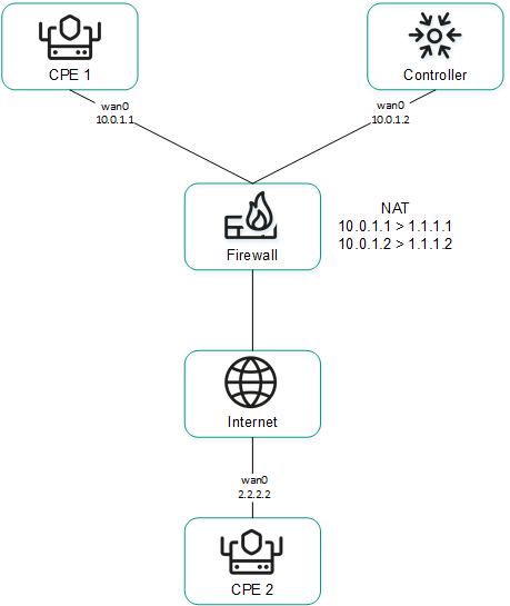
CPE 1 and the controller are behind NAT and are connected to CPE 2
Sending IP addresses of SD-WAN interfaces of the WAN type located in an isolated network to the controller
SD-WAN interfaces of the WAN type may be on an isolated network without the possibility of establishing a management session with the controller, but they can be used to establish links. In this case, the controller cannot obtain information about the IP addresses of isolated SD-WAN interfaces of the WAN type and use it to establish links between CPE devices.
In the figure below, CPE 1 and CPE 2 have two SD-WAN interface of the WAN type each, but they can establish a management session with the controller only through wan0 because wan1 is on an isolated network (MPLS) that does not have access to the controller. However, both wan1 interfaces can be used to establish links.
If the link used to interact with the controller fails for one of the CPE devices, all other links also cannot be used, even if they remain operational, because the Controller eliminates the device from the topology.
The IP addresses of isolated SD-WAN interfaces of the WAN type are sent to the controller through the orchestrator.
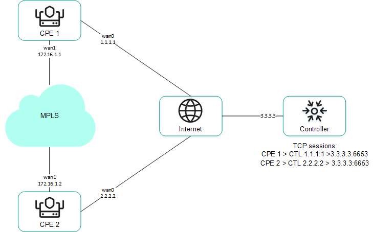
CPE 1 and CPE 2 are connected with each other through MPLS and with the controller through the Internet.
Page topPackage fragmentation
Kaspersky SD-WAN checks whether fragmentation of traffic packets is supported on CPE devices. A packet fragmentation test is started automatically. When each CPE device is enabled, it sends two ICMP requests to the IP addresses that you specified when creating or editing SD-WAN interfaces of the WAN type.
The ICMP requests have a packet size of 1600 bytes. If at least one of these requests receives a response, a conclusion is made that the CPE device supports packet fragmentation. You can view the fragmentation test result in the Fragmentation column of the CPE device table or the link table.
Page topTraffic queues on SD-WAN interfaces
A maximum of 8 traffic queues can be used on SD-WAN interfaces. For each traffic queue, you must specify the minimum and maximum bandwidth as a percentage of the total bandwidth set for the SD-WAN interface. The sum total of all minimum bandwidth values specified for traffic queues may not exceed 100%.
The traffic queues are strict priority and unreserved bandwidth is first offered to traffic from the higher-priority queue. Each traffic queue is guaranteed certain minimum bandwidth in accordance with its specified minimum bandwidth value. An upper limit on the maximum bandwidth for higher-priority queues is necessary to allow traffic from lower-priority traffic queues to still be transmitted.
You can configure traffic queues when creating SD-WAN interfaces of the WAN type or editing SD-WAN interfaces of the WAN or LAN type.
Service providers can use different quality of service policies to mark traffic queues in their networks and meet SLA requirements for the passage of client traffic. Therefore, when simultaneously connecting to the networks of different service providers, CPE devices can relabel traffic of different queues for each SD-WAN interface of the WAN type. To configure relabeling, you must change the type of service (ToS) when configuring queues on an SD-WAN interface.
You can only change the ToS values of external headers of traffic packets originating from SD-WAN interfaces of the WAN type. ToS values of internal traffic packet headers cannot be edited.
Page topCreating an SD-WAN interface of the WAN type
You can create an SD-WAN interface of the WAN type in a CPE template or on a CPE device. An SD-WAN interface of the WAN type created in a CPE template is automatically created on all CPE devices that are using this CPE template.
To create an SD-WAN interface of the WAN type:
- Create an SD-WAN interface of the WAN type in one of the following ways:
- If you want to create an SD-WAN interface of the WAN type in a CPE template, go to the SD-WAN → CPE templates menu section, click the CPE template, and select the SD-WAN settings → Interfaces tab.
- If you want to create an SD-WAN interface of the WAN type on a CPE device, go to the SD-WAN → CPE menu section, click the CPE device, and select the SD-WAN settings → Interfaces tab.
A table of SD-WAN interfaces is displayed.
- Click + SD-WAN interface.
- This opens a window; in that window, in the OpenFlow interface field, enter the number of the OpenFlow port that you are creating on the virtual switch.
- In the Interface (alias) field, enter the name of the created network interface, which the SD-WAN interface of the WAN type is mapped to.
- In the Maximum rate field, enter the maximum speed of the SD-WAN interface of the WAN type in Mbps. Range of values: 1 to 100,000. Default value:
1000. - Configure the availability check of the WAN to which the SD-WAN interface of the WAN type is connected:
- Specify the host for checking WAN availability. To do so, under IP for tracking, enter the IP address of the host and click + Add.
The host is specified and displayed under IP for tracking. You can specify multiple hosts or delete a host. To delete a host, click the delete icon
next to it. - In the IP for fragmentation check field, enter the IPv4 address of the host up to which fragmentation support is checked. Default value: 1.1.1.1.
- In the Reliability field, enter the minimum number of successful checks that makes the WAN available. Default value:
1.Make sure that the number of hosts does not exceed the number of IP addresses specified under IP for tracking. Otherwise, the WAN will always be considered unavailable.
- In the Interval field, enter the WAN check interval in seconds. Range of values: 1 to 600. Default value:
2. - In the Count field, enter the number of requests to hosts within one WAN check. Range of values: 1 to 600. Default value:
2. - In the Timeout field, enter the time to wait for a response from hosts, in milliseconds. Range of values: 1 to 100,000. Default value:
2000. - In the Down field, enter the number of unsuccessful checks that makes the WAN unavailable. Range of values: 1 to 600. Default value:
3. - In the Up field, enter the number of successful checks that makes the WAN available. Range of values: 1 to 600. Default value:
2. - In the Speed monitoring drop-down list, select whether the speed of the SD-WAN interface of the WAN type is being measured:
- Yes
- No Default value.
- Specify the host for checking WAN availability. To do so, under IP for tracking, enter the IP address of the host and click + Add.
- If you want to configure traffic queues on the SD-WAN interface of the WAN type:
- Select the QoS tab.
A table of traffic queues is displayed.
- In the Remap ToS column, select the Type of Service value of external headers of traffic packets for each queue.
- In the Minimum rate (%) column, specify the minimum traffic bandwidth for the queue as a percentage of the maximum speed of the SD-WAN interface of the WAN type. The sum total in a column may not exceed 100.
- In the Maximum rate (%) column, specify the maximum traffic bandwidth for the queue as a percentage of the maximum speed of the SD-WAN interface of the WAN type. This setting is used to prevent traffic of high-priority queues from indefinitely preempting traffic of low-priority queues.
The maximum speed of the SD-WAN interface of the WAN type is specified at step 5 of these instructions.
- Select the QoS tab.
- If you want to configure the sending of information about the SD-WAN interface of the WAN type to the controller:
- Select the NAT and disjoint WAN underlay tab.
- In the State drop-down list, select one of the following values:
- Disabled if you do not want information about the SD-WAN interface of the WAN type to be sent to the controller.
- NAT/PAT if the SD-WAN interface of the WAN type is behind NAT or PAT and needs to be assigned a public IP address and UDP port number, which must be sent to the controller.
- Disjoint WAN underlay if the SD-WAN interface of the WAN type is connected to an isolated network and its IP address must be communicated to the controller.
- If in the State drop-down list, you selected NAT/PAT, follow these steps:
- In the Real IP field, enter the public IPv4 address of the SD-WAN interface of the WAN type.
- In the Real GENEVE UDP port field, enter the UDP port number of the SD-WAN interface of the WAN type. Range of values: 1 to 65,535.
- If in the State drop-down list you selected Disjoint WAN underlay, enter the IPv4 address of the SD-WAN interface of the WAN type in the IP address field.
- If SD-WAN interfaces of the WAN type of the CPE device are connected to different networks, for example, the internet and a private MPLS network, you can change the IP addresses and TCP port numbers of controller nodes on individual SD-WAN interfaces of the WAN type. You can change the IP addresses and TCP port numbers of the controller nodes while configuring the controller nodes of an SD-WAN instance. This automatically changes the IP addresses and TCP port numbers of controller nodes on all CPE devices that are added to the SD-WAN instance. The IP addresses and TCP port numbers specified on the SD-WAN interface of the WAN type take precedence over the IP addresses and TCP port numbers specified when configuring the controller nodes of the SD-WAN instance.
To change the IP addresses and TCP port numbers of controller nodes on the SD-WAN interface of the WAN type:
- Select the Controllers tab.
- Select the Rewrite controllers IP/port check box. This check box is cleared by default.
- In the Number of controllers drop-down list, select the number of controller nodes.
You need to specify the number of controller nodes that you deployed when you deployed the SD-WAN instance. Otherwise, an error occurs and the settings remain unchanged.
- In the IP address field, enter the IPv4 address of the controller node. The number of fields corresponds to the value that you selected in the Number of controllers drop-down list.
- In the Port field, enter the base port number of the controller node. Range of values: 1 to 65,535. Default value:
6653. The number of fields corresponds to the value that you selected in the Number of controllers drop-down list.Along with the base port of the controller node, ports with the next three consecutive numbers are automatically specified. For example, if you enter the
6653as the base port number, ports 6654, 6655, and 6656 are automatically specified.
For the changes to take effect, you need to restart the CPE device after changing the IP addresses and TCP port numbers of controller nodes on the SD-WAN interface of the WAN type.
- Click Create.
The SD-WAN interface of the WAN type is created and displayed in the table.
- In the upper part of the settings area, click Save to save the settings of the CPE template or CPE device.
Editing an SD-WAN interface
You can edit an SD-WAN interface in a CPE template or on a CPE device. You cannot edit the name of an SD-WAN interface. When editing an SD-WAN interface of the LAN type, you can only configure the maximum speed and traffic queues. An SD-WAN interface edited in the CPE template is automatically modified on all CPE devices that use this CPE template.
To edit an SD-WAN interface:
- Edit an SD-WAN interface in one of the following ways:
- If you want to edit an SD-WAN interface in a CPE template, go to the SD-WAN → CPE templates menu section, click the CPE template, and select the SD-WAN settings → Interfaces tab.
- If you want to edit an SD-WAN interface on a CPE device, go to the SD-WAN → CPE menu section, click the CPE device, and select the SD-WAN settings → Interfaces tab. If you want to edit an SD-WAN interface inherited from the CPE template, select the Override check box next to that interface.
A table of SD-WAN interfaces is displayed.
- Click Edit next to the SD-WAN interface that you want to edit.
- This opens a window; in that window, edit the SD-WAN interface settings, if necessary. For a description of the settings, see the instructions for creating an interface of the WAN type.
- Click Save.
The SD-WAN interface is edited and updated in the table.
- In the upper part of the settings area, click Save to save the settings of the CPE template or CPE device.
Disabling or enabling an SD-WAN interface
You can disable or enable an SD-WAN interface in a CPE template or on a CPE device. An SD-WAN interface enabled or disabled in a CPE template is automatically enabled or disabled on all CPE devices that use this CPE template.
To disable or enable an SD-WAN interface:
- Disable or enable an SD-WAN interface in one of the following ways:
- If you want to enable or disable an SD-WAN interface in a CPE template, go to the SD-WAN → CPE templates menu section, click the CPE template, and select the SD-WAN settings → Interfaces tab.
- If you want to enable or disable an SD-WAN interface on a CPE device, go to the SD-WAN → CPE menu section, click the CPE device, and select the SD-WAN settings → Interfaces tab. If you want to disable or enable an SD-WAN interface inherited from the CPE template, select the Override check box next to that SD-WAN interface.
A table of SD-WAN interfaces is displayed.
- Click Disable or Enable next to the SD-WAN interface that you want to disable or enable.
The SD-WAN interface is disabled or enabled and updated in the table.
- In the upper part of the settings area, click Save to save the settings of the CPE template or CPE device.
Deleting an SD-WAN interface of the WAN type
You can delete an SD-WAN interface of the WAN type in a CPE template or on a CPE device. An SD-WAN interface of the WAN type deleted in a CPE template is automatically deleted on all CPE devices that are using this CPE template. You cannot delete an SD-WAN interface inherited from the CPE template on a CPE device, or delete an SD-WAN interface of the LAN type.
Deleted SD-WAN interfaces of the WAN type cannot be restored.
To delete an SD-WAN interface of the WAN type:
- Delete an SD-WAN interface of the WAN type in one of the following ways:
- If you want to delete an SD-WAN interface of the WAN type in a CPE template, go to the SD-WAN → CPE templates menu section, click the CPE template, and select the SD-WAN settings → Interfaces tab.
- If you want to delete an SD-WAN interface of the WAN type on a CPE device, go to the SD-WAN → CPE menu section, click the CPE device, and select the SD-WAN settings → Interfaces tab.
A table of SD-WAN interfaces is displayed.
- Click Delete next to the SD-WAN interface of the WAN type that you want to delete.
- In the confirmation window, click Delete.
The SD-WAN interface of the WAN type is deleted and is no longer displayed in the table.
- In the upper part of the settings area, click Save to save the settings of the CPE template or CPE device.
Managing service interfaces
Service interfaces are mapped to OpenFlow ports and are used to connect a CPE device to transport services. A service interface cannot be mapped to an OpenFlow port that is already mapped to an SD-WAN interface of the WAN type.
If you want to filter traffic packets on a service interface, you can create an Access Control List (ACL) interface that is mapped to this service interface. The ACL interface applies the specified traffic filter to the service interface. A single service interface can be mapped to at most four ACL interfaces.
To display the table of service interfaces, go to the Infrastructure menu section, click Management → Configuration menu next to the controller, and go to the Service interfaces section. Information about service interfaces is displayed in the following columns of the table:
- Port is the number of the OpenFlow port to which the service interface is mapped to.
- Type is the traffic classification type on the service interface.
- Access
- VLAN
- Q-in-Q
- ACL
- Description is a brief description of the service interface.
- VLAN is the outer VLAN tag of the service interface. The value in this column is only displayed for service interfaces with traffic classification types VLAN and Q-in-Q.
- Inner VLAN is the inner VLAN tag of the service interface. The value in this column is only displayed for service interfaces with traffic classification type Q-in-Q.
- Filter is the traffic filter for the ACL interface. The value in this column is only displayed for service interfaces with traffic classification type ACL.
- Name is the name of the service interface.
The actions you can perform with the table are described in the Managing solution component tables instructions.
Creating a service interface
To create a service interface:
- In the menu, go to the Infrastructure section.
This opens the resource management page. By default, the Network resources tab is selected, which displays the table of controllers.
- Click Management → Configuration menu next to the controller.
This opens the controller configuration menu. By default, you are taken to the Controller nodes section, which displays a table of controller nodes.
- Go to the Service interfaces section.
A table of service interfaces and ACL interfaces is displayed.
- In the Switch and Port drop-down lists, select the CPE device and the OpenFlow port to which the service interface is mapped.
- Click Create service interface.
- This opens a window; in that window, in the Type drop-down list, select the type of traffic classification on the service interface:
- Access Default value.
- VLAN If you select this option, in the VLAN ID field, enter the outer VLAN tag of the service interface. Range of values: 1 to 4094.
- Q-in-Q If you select this option, do the following:
- In the VLAN ID field, enter the outer VLAN tag of the service interface. Range of values: 1 to 4094.
- In the Inner VLAN ID field, enter the inner VLAN tag of the service interface. Range of values: 1 to 4094.
- ACL is used when creating an ACL interface.
- If necessary, enter a brief description of the service interface in the Description field.
- Click Create.
The service interface is created and displayed in the table.
Page topCreating an ACL interface
To create an ACL interface:
- In the menu, go to the Infrastructure section.
This opens the resource management page. By default, the Network resources tab is selected, which displays the table of controllers.
- Click Management → Configuration menu next to the controller.
This opens the controller configuration menu. By default, you are taken to the Controller nodes section, which displays a table of controller nodes.
- Go to the Service interfaces section.
A table of service interfaces and ACL interfaces is displayed.
- In the Switch and Port drop-down lists, select the CPE device and the OpenFlow port to which the created service interface is mapped.
- Click + Create service interface.
- This opens a window; in that window, in the Type drop-down list, select ACL.
- In the Service interface drop-down list, select the service interface to which the ACL interface is mapped.
- In the Traffic fliter drop-down list, select the created traffic filter for the ACL interface. You can use the same traffic filter for multiple ACL interfaces.
- In the Sequence drop-down list, select the sequential number of the ACL interface. Traffic is directed first to the ACL interface with the lowest number. If the filter used on an ACL interface does not take in the traffic, the traffic is sent to the second ACL interface, and so on.
Range of values: 1 to 4. Two ACL interfaces with the same serial number cannot be mapped to the same service interface.
- If necessary, enter a brief description of the ACL interface in the Description field.
- Click Create.
The ACL interface is created and displayed in the table.
Viewing the usage of a service interface and an ACL interface
You can view which transport services are using a service interface or an ACL interface. A service interface or ACL interface that is in use cannot be deleted.
To view the usage of a service interface or ACL interface:
- In the menu, go to the Infrastructure section.
This opens the resource management page. By default, the Network resources tab is selected, which displays the table of controllers.
- Click Management → Configuration menu next to the controller.
- Go to the Service interfaces section.
A table of service interfaces and ACL interfaces is displayed.
- Click Management → Show usage next to the service interface or ACL interface for which you want to view usage information.
This opens a window with a table of transport services that are using the service interface or ACL interface.
tPage topDeleting a service interface and an ACL interface
You cannot delete a service interface or an ACL interface if it is being used by at least one transport service. You must view the usage of a service interface or ACL interface and make sure that it is not being used.
Deleted service interfaces and ACL interfaces cannot be restored.
To delete a service interface or an ACL interface:
- In the menu, go to the Infrastructure section.
This opens the resource management page. By default, the Network resources tab is selected, which displays the table of controllers.
- Click Management → Configuration menu next to the controller.
- Go to the Service interfaces section.
A table of service interfaces and ACL interfaces is displayed.
- Click Management → Delete next to the service interface or ACL interface that you want to delete.
- In the confirmation window, click Delete.
The service interface or ACL interface is deleted and is no longer displayed in the table.
Page topManaging OpenFlow port groups
OpenFlow ports are interfaces of the overlay SDN that are automatically created at the same time as the SD-WAN interfaces. The controller uses OpenFlow ports to control network traffic. You can create service interfaces and UNIs that are mapped to OpenFlow ports.
OpenFlow ports can be combined into OpenFlow port groups and used when creating P2M and M2M transport services. When you add an OpenFlow port group to a transport service, this automatically creates service interfaces mapped to the OpenFlow ports, and then these service interfaces are added to the transport service. Using groups of OpenFlow ports eliminates the need to manually create service interfaces and add them to transport services.
To display the table of OpenFlow port groups, go to the Infrastructure menu section, click Management → Configuration menu next to the controller, and go to the OpenFlow groups section. Information about groups of OpenFlow ports is displayed in the following columns of the table:
- Name is the name of the OpenFlow port group.
- Ports are OpenFlow ports that have been added to the OpenFlow ports group.
The actions you can perform with the table are described in the Managing solution component tables instructions.
Creating an OpenFlow port group
To create a group of OpenFlow ports:
- In the menu, go to the Infrastructure section.
This opens the resource management page. By default, the Network resources tab is selected, which displays the table of controllers.
- Click Management → Configuration menu next to the controller.
- Go to the OpenFlow groups section.
A table of groups of OpenFlow ports is displayed.
- In the upper part of the page, click + OpenFlow group.
- This opens a window; in that window, in the Name field, enter the name of the OpenFlow port group.
- In the Switch and Port drop-down lists, select the CPE device and OpenFlow port that you want to add to the OpenFlow port group.
- Click Create.
The group of OpenFlow interfaces is created and displayed in the table.
Page topEditing an OpenFlow port group
To edit a group of OpenFlow ports:
- In the menu, go to the Infrastructure section.
This opens the resource management page. By default, the Network resources tab is selected, which displays the table of controllers.
- Click Management → Configuration menu next to the controller.
- Go to the OpenFlow groups section.
A table of groups of OpenFlow ports is displayed.
- Click Management → Edit next to the group of OpenFlow ports that you want to edit.
- This opens a window; in that window, if necessary, edit the name of the OpenFlow port group and add or delete OpenFlow ports.
- Click Save.
The OpenFlow port group is modified and updated in the table.
Page topDeleting an OpenFlow port group
Deleted groups of OpenFlow ports cannot be restored.
To delete a group of OpenFlow ports:
- In the menu, go to the Infrastructure section.
This opens the resource management page. By default, the Network resources tab is selected, which displays the table of controllers.
- Click Management → Configuration menu next to the controller.
- Go to the OpenFlow groups section.
A table of groups of OpenFlow ports is displayed.
- Click Management → Delete next to the group of OpenFlow ports that you want to delete.
- In the confirmation window, click Delete.
The group of OpenFlow ports is deleted and is no longer displayed in the table.
Page topConfiguring a UNI for connecting CPE devices to network services
UNIs are mapped to OpenFlow ports and are used to connect a CPE device to network services. A UNI cannot be mapped to an OpenFlow port that is already mapped to an SD-WAN interface of the WAN type.
To avoid creating an UNI on each individual CPE device, you can create a UNI in a UNI template and then apply the UNI template to CPE devices when adding or manually registering them. If you edit a UNI in a UNI template, the UNI is automatically modified on all CPE devices that are using this UNI template.
When creating a UNI, a service interface is automatically created for it.
Managing UNI templates
The table of UNI templates is displayed in the SD-WAN → UNI templates section. Information about UNI templates is displayed in the following columns of the table:
- ID is the ID of the UNI template.
- Name is the name of the UNI template.
- Used indicates whether the UNI template is being used by CPE devices:
- Yes
- No
- Updated is the date and time when the UNI template settings were last modified.
- User is the name of the user which created the UNI template.
- Owner is the tenant to which the UNI template belongs.
The actions that you can perform with the table are described in the Managing solution component tables instructions.
UNI template settings are displayed on the following tabs:
- Information is the basic information about the UNI template. You can edit the name of the UNI template in the Name field.
- UNIs are UNIs that were created in the UNI template.
Creating a UNI template
To create a UNI template:
- In the menu, go to the SD-WAN → UNI templates subsection.
A table of UNI templates is displayed.
- In the upper part of the page, click + UNI template.
- This opens a window; in that window, enter the name of the UNI template.
- Click Create.
The UNI template is created and displayed in the table.
You need to configure the created UNI template. For a description of UNI template tabs, see the Managing UNI templates section.
Page topDeleting a UNI template
Deleted UNI templates cannot be restored.
To delete a UNI template:
- In the menu, go to the SD-WAN → UNI templates subsection.
A table of UNI templates is displayed.
- Click the UNI template that you want to delete.
The settings area is displayed in the lower part of the page. You can expand the settings area to fill the entire page by clicking the expand icon
. By default, the Information tab is selected, which displays the UNI template name and the tenant to which the UNI template is assigned. - In the upper part of the settings area, under Actions, click Delete.
- In the confirmation window, click Delete.
The UNI template is deleted and is no longer displayed in the table.
Page topManaging UNIs
Managing UNIs in a UNI template
To display the table of UNIs in a UNI template, go to the SD-WAN → UNI templates menu section, click the UNI template, and select the UNIs tab. Information about UNIs is displayed in the following columns of the table:
- Name is the name of the UNI.
- OpenFlow interface is the number of the OpenFlow port mapped to the UNI.
- Encapsulation is the traffic classification type on the UNI:
- Access
- VLAN
- Q-in-Q
- Actions contains the actions can be performed with the UNI.
Managing UNIs on a CPE device
To display the list of UNIs on a CPE device, go to the SD-WAN → CPE menu section, click the CPE device, and select the UNIs tab.
Creating a UNI
You can create a UNI in a UNI template or on a CPE device. A UNI created in the UNI template is automatically created on all CPE devices that use this UNI template.
To create a UNI:
- Create a UNI in one of the following ways:
- If you want to create a UNI in a UNI template, go to the SD-WAN → UNI templates menu section, click the UNI template, and select the UNIs tab.
- If you want to create an UNI on a CPE device, go to the SD-WAN → CPE menu section, click the CPE device, and select the UNIs tab.
A table or list of UNIs is displayed.
- Click + UNI.
- This opens a window; in that window, in the Name field, enter the name of the UNI.
- Specify the OpenFlow port to which the UNI is mapped in one of the following ways:
- If you are creating a UNI in a UNI template, enter the OpenFlow port number in the OpenFlow interface field.
- If you are creating a UNI on a CPE device, select the OpenFlow port in the Port drop-down list.
- In the Encapsulation drop-down list, select the traffic classification type on the UNI:
- Access Default value.
- VLAN If you select this option, in the VLAN ID field, enter the outer VLAN tag of the UNI. Range of values: 1 to 4094.
- Q-in-Q If you select this option, do the following:
- In the VLAN ID field, enter the outer VLAN tag of the UNI. Range of values: 1 to 4094.
- In the Inner VLAN ID field, enter the inner VLAN tag of the UNI. Range of values: 1 to 4094.
- If you are creating a UNI on a CPE device, in the QoS drop-down list, select a created quality of service rule for the UNI.
- Click Create.
The UNI is created and displayed in the table or list.
- In the upper part of the settings area, click Save to save the settings of the UNI template or CPE device.
Viewing UNI usage
You can see which network services are using the UNI on a CPE device. If a UNI template is in use, it cannot be deleted.
To view UNI usage:
- In the menu, go to the SD-WAN → CPE section.
A table of CPE devices is displayed.
- Click the CPE device on which you want to view UNI usage.
The settings area is displayed in the lower part of the page. You can expand the settings area to fill the entire page by clicking the expand icon
. By default, the Configuration tab is selected, which displays general information about the CPE device. This tab also displays the table of Out-of-band management tasks being performed by the orchestrator. - Select the UNIs tab.
A list of UNIs is displayed.
- Click Management → Show usage next to the UNI whose usage you want to view.
This opens a window with a table of network services that are using the UNI.
Page topEditing a UNI
You can edit a UNI in a UNI template. A UNI edited in the UNI template is automatically modified on all CPE devices that use this UNI template.
To edit a UNI:
- In the menu, go to the SD-WAN → UNI templates subsection.
A table of UNI templates is displayed.
- Click the UNI template in which you want to edit a UNI.
The settings area is displayed in the lower part of the page. You can expand the settings area to fill the entire page by clicking the expand icon
. By default, the Information tab is selected, which displays the UNI template name and the tenant to which the UNI template is assigned. - Select the UNI tab.
A table of UNIs is displayed.
- Click Edit next to the UNI that you want to edit.
- This opens a window; in that window, if necessary, edit the UNI settings. For a description of the settings, see the instructions for creating a UNI.
- Click Save.
The UNI is modified and updated in the table.
- In the upper part of the settings area, click Save to save UNI template settings.
Deleting a UNI
You can delete a UNI in a UNI template or on a CPE device. A UNI deleted in the UNI template is automatically deleted on all CPE devices that use this UNI template.
Deleted UNIs cannot be restored.
Deleting a UNI in a UNI template
To delete a UNI in a UNI template:
- In the menu, go to the SD-WAN → UNI templates subsection.
A table of UNI templates is displayed.
- Click the UNI template in which you want to delete a UNI.
The settings area is displayed in the lower part of the page. You can expand the settings area to fill the entire page by clicking the expand icon
. By default, the Information tab is selected, which displays the UNI template name and the tenant to which the UNI template is assigned. - Select the UNIs tab.
A table of UNIs is displayed.
- Click Delete next to the UNI that you want to delete.
The UNI is deleted and is no longer displayed in the table.
- In the upper part of the settings area, click Save to save UNI template settings.
Deleting an UNI on a CPE device
You cannot delete a UNI if it is being used by at least one network service. You need to look up the usage of the UNI and make sure that it is not in use.
To delete a UNI on a CPE device:
- In the menu, go to the SD-WAN → CPE section.
A table of CPE devices is displayed.
- Click the CPE device on which you want to delete a UNI.
The settings area is displayed in the lower part of the page. You can expand the settings area to fill the entire page by clicking the expand icon
. By default, the Configuration tab is selected, which displays general information about the CPE device. This tab also displays the table of Out-of-band management tasks being performed by the orchestrator. - Select the UNIs tab.
A list of UNIs is displayed.
- Click Management → Delete next to the UNI that you want to delete.
- In the confirmation window, click Delete.
The UNI is deleted and is no longer displayed in the table.
- In the upper part of the settings area, click Save to save CPE device settings.
Adding a static route
In addition to dynamic route exchange between CPE devices and external network devices via BGP and OSPF protocols, Kaspersky SD-WAN supports static IPv4 routes. You can add a static route in a CPE template or on a CPE device. A static route added to the CPE template is automatically added to all CPE devices that use this CPE template.
To add a static route:
- Add a static route in one of the following ways:
- If you want to add a static route in a CPE template, go to the SD-WAN → CPE templates menu section, click the CPE template, and select the Static routes tab.
- If you want to add a static route on a CPE device, go to the SD-WAN → CPE menu section, click the CPE device, and select the Static routes tab and select the Override check box.
A table of static routes is displayed.
- Click the add static route icon .
- In the Interface drop-down list, select the created source network interface of the static route.
- In the Target field, enter the destination IPv4 address of the static route.
- If necessary, in the IPv4 netmask field, enter the IPv4 address of the destination subnet of the static route.
- In the Gateway field, enter the IP address of the gateway of the static route.
- In the Metric field, enter a metric for the static route. Default value:
0. - In the MTU field, enter the MTU value for the static route.
- In the Type drop-down list, select the type of the static route:
- unicast. Default value.
- local
- broadcast
- multicast
- unreachable
- prohibit
- blackhole
- anycast
- If you want to add a static route in a virtual routing and forwarding table, in the VRF drop-down list, select a created virtual routing and forwarding table. You must add the static route to the virtual routing table that contains the network interface of the source of the static route.
The static route is added and displayed in the table. You can add multiple static routes or delete a static route. To remove a static route, click the delete icon
 next to it.
 - In the upper part of the settings area, click Save to save the settings of the CPE template or CPE device.
Filtering routes and traffic packets
You can use the following mechanisms for route filtering when working with the BGP and OSPF protocols, and for filtering traffic packets when working with the PIM protocol:
- Access control lists (ACL) allow or deny the specified IPv4 prefixes.
- Prefix lists are an extended version of access control lists. These additionally allow or block IPv4 prefixes in the specified prefix length range. You can use prefix lists in route maps.
- Route maps are an extended version of prefix lists. Route maps additionally modify attribute values.
You can create rules in access control lists, prefix lists, and route maps. Each rule is numbered. The rule with the lowest sequence number is the first to be applied to an IPv4 prefix. If none of the rules can be applied, the IPv4 prefix is denied.
Managing access control lists (ACLs)
The table of access control lists is displayed in the CPE template and on the CPE device:
- To display the table of access control lists in a CPE template, go to the SD-WAN → CPE templates menu section, click the CPE template, and select the Routing filters → Access control lists tab.
- To display the table of access control lists on a CPE device, go to the SD-WAN → CPE menu section, click the CPE device, and select the Routing filters → Access control lists tab.
Information about access control lists is displayed in the following columns of the table:
- Name is the name of the access control list.
- Inherited indicates whether the access control list is inherited from the CPE template:
- Yes
- No
This column is displayed only on the CPE device.
- Sequence is the sequence number of the rule in the access control list. The rule with the lowest sequence number is the first to be applied to the IPv4 prefix by the access control list.
- Network is the IPv4 prefix to which the access control list applies the rule.
- Action is the action that the rule performs on the IPv4 prefix:
- Permit allows the IPv4 prefix.
- Deny — deny the IPv4 prefix.
- Management contains the actions that can be performed on the access control list.
Creating an access-control list
You can create an access control list in a CPE template or on a CPE device. An access control list created in the CPE template is automatically created on all CPE devices that use this CPE template.
To create an access control list:
- Create an access control list in one of the following ways:
- If you want to create an access control list in a CPE template, go to the SD-WAN → CPE templates menu section, click the CPE template, and select the Routing filters → Access control lists tab.
- If you want to create an access control list on a CPE device, go to the SD-WAN → CPE menu section, click the CPE device, and select the Routing filters → Access control lists tab and select the Override check box.
A table of access control lists is displayed.
- Click + Access control list.
- This opens a window; in that window, in the Name field, enter the name of the access control list. Maximum length: 50 characters. Do not use spaces in this field.
- Create a rule in the access control list:
- Click + Rule.
- In the Sequence field, enter the sequential number of the rule. The rule with the lowest sequence number is the first to be applied to the IPv4 prefix by the access control list. Range of values: 1 to 4,294,967,295.
- In the Network drop-down list, select the type of the rule:
- Any network for a rule that allows or denies all IPv4 prefixes.
- IP/mask for a rule that allows or denies the specified IPv4 prefix. Default value. If you select this value, enter the IPv4 prefix in the field that is displayed.
- In the Action drop-down list, select the action that the rule performs with the IPv4 prefix:
The rule is created. You can create multiple rules or delete a rule.
To delete a rule, click the delete icon next to it. - Click Create.
The access control list is created and displayed in the table.
- In the upper part of the settings area, click Save to save the settings of the CPE template or CPE device.
Editing an access control list
You can edit an access control list in the CPE template or on a CPE device. An access control list edited in the CPE template is automatically modified on all CPE devices that use this CPE template.
To edit an access control list:
- Edit an access control list in one of the following ways:
- If you want to edit an access control list in a CPE template, go to the SD-WAN → CPE templates menu section, click the CPE template, and select the Routing filters → Access control lists tab.
- If you want to edit an access control list on a CPE device, go to the SD-WAN → CPE menu section, click the CPE device, and select the Routing filters → Access control lists tab and select the Override check box.
A table of access control lists is displayed.
- Click Edit next to the access control list that you want to edit.
- This opens a window; in that window, if necessary, edit the settings of the access control list. For a description of the settings, see the instructions for creating an access control list.
- Click Save.
The access control list is modified and updated in the table.
- In the upper part of the settings area, click Save to save the settings of the CPE template or CPE device.
Deleting an access control list
You can delete an access control list in the CPE template or on a CPE device. An access control list deleted in the CPE template is automatically deleted on all CPE devices that use this CPE template.
Deleted access control lists cannot be restored.
To delete an access control list:
- Delete an access control list in one of the following ways:
- If you want to delete an access control list in a CPE template, go to the SD-WAN → CPE templates menu section, click the CPE template, and select the Routing filters → Access control lists tab.
- If you want to delete an access control list on a CPE device, go to the SD-WAN → CPE menu section, click the CPE device, and select the Routing filters → Access control lists tab and select the Override check box.
A table of access control lists is displayed.
- Click Delete next to the access control list that you want to delete.
- In the confirmation window, click Delete.
The access control list is deleted and is no longer displayed in the table.
- In the upper part of the settings area, click Save to save the settings of the CPE template or CPE device.
Managing prefix lists
The table of prefix lists is displayed in the CPE template and on the CPE device:
- To display the table of prefix lists in a CPE template, go to the SD-WAN → CPE templates menu section, click the CPE template, and select the Routing filters → Prefix lists tab.
- To display the table of prefix lists on a CPE device, go to the SD-WAN → CPE menu section, click the CPE device, and select the Routing filters → Prefix lists tab.
Information about prefix lists is displayed in the following columns of the table:
- Name is the name of the prefix list.
- Inherited indicates whether the prefix list is inherited from the CPE template:
- Yes
- No
This column is displayed only on the CPE device.
- Sequence is the sequence number of the rule in the prefix list. The rule with the lowest sequence number is the first to be applied to the IPv4 prefix by the prefix list.
- Network is the IPv4 prefix to which the prefix list applies the rule.
- Action is the action that the rule performs on the IPv4 prefix:
- Permit allows the IPv4 prefix.
- Deny blocks the IPv4 prefix.
- Greater or equal is starting value of the prefix length range to which the prefix list applies the rule.
- Less or equal is the ending value of the prefix length range to which the prefix list applies the rule.
- Management contains the actions that can be performed on the prefix list.
Creating a prefix list
You can create a prefix list in the CPE template or on a CPE device. A prefix list created in the CPE template is automatically created on all CPE devices that use this CPE template.
To create a prefix list:
- Create a prefix list in one of the following ways:
- If you want to create a prefix list in a CPE template, go to the SD-WAN → CPE templates menu section, click the CPE template, and select the Routing filters → Prefix lists tab.
- If you want to create a prefix list on a CPE device, go to the SD-WAN menu section, click the CPE device, select the Routing filters → Prefix lists tab, and select the Override check box.
A table of prefix lists is displayed.
- Click + Prefix list.
- This opens a window; in that window, in the Name field, enter the name of the prefix list. Maximum length: 50 characters. Do not use spaces in this field.
- Create a rule in the prefix list:
- Click + Rule.
- In the Sequence field, enter the sequential number of the rule. The rule with the lowest sequence number is the first to be applied to the IPv4 prefix by the prefix list. Range of values: 1 to 4,294,967,295.
- In the Network drop-down list, select the type of the rule:
- Any network for a rule that allows or denies all IPv4 prefixes.
- IP/mask for a rule that allows or denies the specified IPv4 prefix. Default value. If you select this value, enter the IPv4 prefix in the field that is displayed.
- In the Action drop-down list, select the action that the rule performs with the IPv4 prefix:
- In the Greater or equal field, enter the starting value of the prefix length range to which the prefix list applies the rule. Range of values: 0 to 32.
- In the Less or equal field, enter the ending value of the prefix length range to which the prefix list applies the rule. Range of values: 0 to 32.
The rule is created. You can create multiple rules or delete a rule.
To delete a rule, click the delete icon next to it. - Click Create.
The prefix list is created and displayed in the table.
- In the upper part of the settings area, click Save to save the settings of the CPE template or CPE device.
Editing a prefix list
You can edit a prefix list in a CPE template or on a CPE device. An prefix list edited in the CPE template is automatically modified on all CPE devices that use this CPE template.
To edit a prefix list:
- Edit a prefix list in one of the following ways:
- If you want to edit a prefix list in a CPE template, go to the SD-WAN → CPE templates menu section, click the CPE template, and select the Routing filters → Prefix lists tab.
- If you want to edit a prefix list on a CPE device, go to the SD-WAN menu section, click the CPE device, select the Routing filters → Prefix lists tab, and select the Override check box.
A table of prefix lists is displayed.
- Click Edit next to the prefix list that you want to edit.
- This opens a window; in that window, if necessary, edit the settings of the prefix list. For a description of the settings, see the instructions for creating a prefix list.
- Click Save.
The prefix list is modified and updated in the table.
- In the upper part of the settings area, click Save to save the settings of the CPE template or CPE device.
Deleting a prefix list
You can delete a prefix list in a CPE template or on a CPE device. A prefix list deleted in the CPE template is automatically deleted on all CPE devices that use this CPE template.
Deleted prefix lists cannot be restored.
To delete a prefix list:
- Delete a prefix list in one of the following ways:
- If you want to delete a prefix list in a CPE template, go to the SD-WAN → CPE templates menu section, click the CPE template, and select the Routing filters → Prefix lists tab.
- If you want to delete a prefix list on a CPE device, go to the SD-WAN → CPE menu section, click the CPE device, select the Routing filters → Prefix lists tab, and select the Override check box.
A table of prefix lists is displayed.
- Click Delete next to the prefix list that you want to delete.
- In the confirmation window, click Delete.
The prefix list is deleted and is no longer displayed in the table.
- In the upper part of the settings area, click Save to save the settings of the CPE template or CPE device.
Managing route maps
The table of route maps is displayed in the CPE template and on the CPE device:
- To display the table of route maps lists in a CPE template, go to the SD-WAN → CPE templates menu section, click the CPE template, and select the Routing filters → Route maps tab.
- To display the table of route maps on a CPE device, go to the SD-WAN → CPE menu section, click the CPE device, and select the Routing filters → Route maps tab.
Information about route maps is displayed in the following columns of the table:
- Name is the name of the route map.
- Inherited indicates whether the route map inherited from CPE template:
- Yes
- No
This column is displayed only on the CPE device.
- Sequence is the sequence number of the rule in the route map. The rule with the lowest sequence number is the first to be applied to the IPv4 prefix by the route map.
- Action is the action that the rule performs on the IPv4 prefix:
- Permit allows the IPv4 prefix.
- Deny blocks the IPv4 prefix.
- Match type is the criterion that makes the route map apply the rule to the IPv4 prefix:
- None applies the rule to all IPv4 prefixes.
- Prefix-List applies the rule to IPv4 prefixes allowed by the specified prefix list.
- Value is a prefix list that must allow the IPv4 prefix to let the route map apply the rule to this IPv4 prefix. This column displays a value only if the Match type column displays Prefix-List.
- Change attribute is the attribute whose value changes the rule.
- New value is the value that the rule sets for the attribute.
- Management contains the actions that can be performed with the route map.
Creating a route map
You can create a route map in a CPE template or on a CPE device. A route map created in the CPE template is automatically created on all CPE devices that use this CPE template.
To create a route map:
- Create a route map in one of the following ways:
- If you want to create a route map in a CPE template, go to the SD-WAN → CPE templates menu section, click the CPE template, and select the Routing filters → Route maps tab.
- If you want to create a route map on a CPE device, go to the SD-WAN → CPE menu section, click the CPE device, select the Routing filters → Route maps tab, and select the Override check box.
A table of route maps is displayed.
- Click + Route map.
- This opens a window; in that window, in the Name field, enter the name of the route map. Maximum length: 50 characters. Do not use spaces in this field.
- Create a rule in the route map:
- Click + Rule.
- In the Sequence field, enter the sequential number of the rule. The rule with the lowest sequence number is the first to be applied to the IPv4 prefix by the route map. Range of values: 1 to 4,294,967,295.
- In the Action drop-down list, select the action that the rule performs with the IPv4 prefix:
- In the Match type drop-down list, select the criterion that makes the route map apply the rule to the IPv4 prefix:
- If in the Match type drop-down list, you selected Prefix-List, in the Change attribute drop-down list, select the attribute that the rule modifies:
The rule is created. You can create multiple rules or delete a rule.
To delete a rule, click the delete icon next to it. - Click Create.
The route map is created and displayed in the table.
- In the upper part of the settings area, click Save to save the settings of the CPE template or CPE device.
Editing a route map
You can edit a route map in a CPE template or on a CPE device. A route map edited in the CPE template is automatically edited on all CPE devices that use this CPE template.
If you want the changes you make to a route map to be immediately applied to the BGP peers or BGP peer groups that use that route map, select the BFD or Soft-reconfiguration inbound check box when creating or editing the BGP peer or BGP peer group.
To edit a route map:
- Edit a route map in one of the following ways:
- If you want to edit a route map in a CPE template, go to the SD-WAN → CPE templates menu section, click the CPE template, and in the displayed settings area, select the Routing filters → Route maps tab.
- If you want to edit a route map on a CPE device, go to the SD-WAN → CPE menu section, click the CPE device, and in the displayed settings area, select the Routing filters → Route maps tab and select the Override check box.
A table of route maps is displayed.
- Click Edit next to the route map that you want to edit.
- This opens a window; in that window, if necessary, edit the route map settings. For a description of the settings, see the instructions for creating a route map.
- Click Save.
The route map is modified and updated in the table.
- In the upper part of the settings area, click Save to save the settings of the CPE template or CPE device.
Deleting a route map
You can delete a route map in a CPE template or on a CPE device. A route map deleted in the CPE template is automatically deleted on all CPE devices that use this CPE template.
Deleted route maps cannot be restored.
To delete a route map:
- Delete a route map in one of the following ways:
- If you want to delete a route map in a CPE template, go to the SD-WAN → CPE templates menu section, click the CPE template, and select the Routing filters → Route maps tab.
- If you want to delete a route map on a CPE device, go to the SD-WAN → CPE menu section, click the CPE device, select the Routing filters → Route maps tab, and select the Override check box.
A table of route maps is displayed.
- Click Delete next to the route map that you want to delete.
- In the confirmation window, click Delete.
The route map is deleted and is no longer displayed in the table.
- In the upper part of the settings area, click Save to save the settings of the CPE template or CPE device.
Route exchange over BGP
Kaspersky SD-WAN supports the BGP (Border Gateway Protocol) dynamic routing protocol for exchanging routing information between CPE devices and external network devices. You can establish internal iBGP (internal BGP) sessions as well as external eBGP (external BGP) sessions.
Creation of individual BGP peers and BGP peer groups is also supported. Dynamic TCP sessions are established with BGP peer groups.
The figures below show examples of BGP being used in the solution:
- Connecting multiple client locations to the L3 SD-WAN network via BGP.
- Connecting CPE devices to the service provider's IP/MPLS network via BGP.
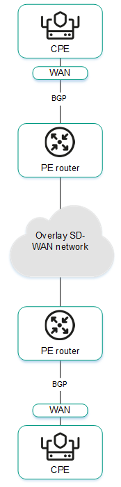
- Using BGP to configure the connectivity of CPE devices within the domain.
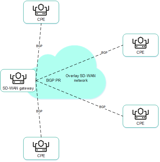
Basic BGP settings
You can specify basic BGP settings in a CPE template or on a CPE device. BGP settings specified in the CPE template are automatically propagated to all CPE devices that use this CPE template.
To modify the basic BGP settings:
- Specify basic BGP settings in one of the following ways:
- If you want to edit the basic BGP settings in a CPE template, go to the SD-WAN → CPE templates menu section, click the CPE template, and select the BGP settings → General settings tab.
- If you want to edit the basic BGP settings on a CPE device, go to the SD-WAN → CPE menu section, click the CPE device, select the BGP settings → General settings tab, and select the Override check box.
Basic BGP settings are displayed.
- In the BGP drop-down list, select Enabled. The default value is Disabled.
- If you want to add BGP routes to the specified virtual routing and forwarding table, in the VRF drop-down list, select a created virtual routing and forwarding table.
- In the AS field, enter the autonomous system number of the CPE device. Range of values: 1 to 4,294,967,295.
- In the Router ID field, enter the IPv4 address that you want to assign to the router ID of the CPE device. If you want to assign an IPv4 address from a specified range of IP addresses:
- Select the Get router ID from IP pool check box. This check box is cleared by default.
- In the IP Pool drop-down list, select a created range of IP addresses.
- If necessary, in the Maximum paths field, enter the maximum number of entries in the routing and forwarding table of the CPE device. Range of values: 1 to 8.
- If necessary, select the following check boxes:
- Select the Always compare MED check box. This check box allows the CPE device to compare the multi-exit discriminator (MED) of routes advertised from different autonomous systems.
You must make sure that this check box is selected on all CPE devices in your autonomous system. Otherwise, exchange of routing information may result in routing loops.
- Select the Graceful restart (helper mode) check box to enable Graceful restart on the CPE device.
These check boxes are cleared by default.
- Select the Always compare MED check box. This check box allows the CPE device to compare the multi-exit discriminator (MED) of routes advertised from different autonomous systems.
- If you do not want the CPE device to exchange IPv4 routes with BGP peers by default, clear the Use default IPv4 unicast routes check box. This check box is selected by default.
- If you want to configure BGP timers:
- Select the BGP timers check box. This check box is cleared by default.
- In the Keepalive field, enter the time interval in seconds that the CPE device uses to send control packets to BGP peers. Range of values: 0 to 65,535.
- In the Holdtime field, enter the time interval in seconds that the CPE device uses when receiving control packets from BGP peers. If no control packets are received from the BGP peer within the specified time, the CPE device considers the peer unavailable. Range of values: 0 to 65,535.
- If you want to configure route redistribution in BGP, under Route redistribution, do the following:
- Select the check boxes next to the route types:
- Kernel to redistribute Kernel routes generated by the operating system of the CPE device.
- Connected to redistribute routes directly connected to network interfaces of CPE device.
- Static to redistribute static routes.
- OSPF to redistribute OSPF routes.
These check boxes are cleared by default.
- In the Route map drop-down list, select a created route map for redistributed routes.
- In the Metric field, enter a metric of redistributed routes. Range of values: 0 to 16,777,214.
- Select the check boxes next to the route types:
- If you want the CPE device to advertise the specified subnet to BGP peers:
- Under Networks, click + Network.
- In the Network field, enter the IPv4 prefix of the subnet.
- In the Route map drop-down list, select a created route map for the subnet.
The subnet is specified and displayed under Networks. You can specify multiple subnets or delete a subnet. To delete a subnet, click the delete icon
next to it. - In the upper part of the settings area, click Save to save the settings of the CPE template or CPE device.
Managing BGP peers
The table of BGP peers is displayed in the CPE template and on the CPE device:
- To display the table of BGP peers in a CPE template, go to the SD-WAN → CPE templates menu section, click the CPE template, and select the BGP settings → Neighbors tab.
- To display the table of BGP peers on a CPE device, go to the SD-WAN → CPE menu section, click the CPE device, and select the BGP settings → Neighbors tab.
Information about BGP peers is displayed in the following columns of the table:
- Neighbor IP is the IPv4 address of the BGP peer.
- Name is the name of the BGP peer.
- Description is a brief description of the BGP peer.
- Inherited indicates whether the BGP peer is inherited from the CPE template:
- Yes
- No
This column is displayed only on the CPE device.
- Remote AS is the autonomous system number of the BGP peer.
- Shutdown indicates whether the BGP peer is disabled and no TCP session is established with it:
- Yes
- No
- Weight is the weight of routes advertised by the BGP peer.
- Management contains the actions that can be performed with the BGP peer.
Creating a BGP peer
You can create a BGP peer in a CPE template or on a CPE device. A BGP peer created in the CPE template is automatically created on all CPE devices that use this CPE template. The maximum number of dynamic BGP peers is 512.
To create a BGP peer:
- Create a BGP peer in one of the following ways:
- If you want to create a BGP peer in a CPE template, go to the SD-WAN → CPE templates menu section, click the CPE template, and select the BGP settings → Neighbors tab.
- If you want to create a BGP peer on a CPE device, go to the SD-WAN → CPE menu section, click the CPE device, select the BGP settings → Neighbors tab, and select the Override check box.
A table of BGP peers is displayed.
- Click + BGP neighbor.
- This opens a window; in that window, in the Name field, enter the name of the BGP peer. Maximum length: 50 characters.
- If you want to disable a BGP peer and prevent establishing a TCP session with it, select the Disable BGP peer check box. This check box is cleared by default.
- In the Neighbor IP field, enter the IPv4 address of the BGP peer.
- In the Remote AS field, enter the autonomous system number of the BGP peer. Range of values: 1 to 4,294,967,295.
- If necessary, enter a brief description of the BGP peer in the Description field.
- If you want the CPE device to use a password when establishing a TCP session with the BGP peer, in the Password field, enter the password. For a TCP session to be successfully established between two BGP peers, they must use the same password. To see the entered password, you can click the show icon
 .
. - If necessary, in the Loopback interface field, enter the IPv4 address of the loopback interface that the CPE device sends to the BGP peer when establishing a TCP session.
- If the TCP session is not established directly between the CPE device and the BGP peer, in the eBGP hops field, enter the number of hops between the CPE device and the BGP peer. Range of values: 1 to 255.
- If you want to configure BGP timers:
- Select the Custom BGP timers check box. This check box is cleared by default.
- In the Keepalive field, enter the time interval in seconds that the CPE device uses to send control packets to the BGP peer. Range of values: 0 to 65,535.
- In the Holdtime field, enter the time interval in seconds that the CPE device uses when receiving control packets from the BGP peer. If no control packets are received from the BGP peer within the specified time, the CPE device considers the peer unavailable. Range of values: 0 to 65,535.
- If you want to use the BFD protocol to detect loss of connectivity, select the BFD check box. This check box is cleared by default. When the check box is selected, changes you make to the route map are immediately applied to a BGP peer if the BGP peer uses this route map. You can select a route map for the BGP peer at step 14 of these instructions.
- If you want to specify advanced settings for the BGP peer:
- Select the Advanced settings tab.
Advanced settings of the BGP peer are displayed.
- If necessary, select the following check boxes:
- Select the Soft-reconfiguration inbound check box to store routes advertised by the BGP peer locally on the CPE device. Using this feature reduces the amount of memory available on the CPE device. When the check box is selected, changes you make to the route map are immediately applied to a BGP peer if the BGP peer uses this route map. You can select a route map for the BGP peer at step 14 of these instructions.
- Select the Attribute unchanged AS path check box to prevent modifying the 'AS path' attribute of routes that the CPE device advertises to the BGP peer.
- Select the Allow AS in check box to let BGP peers advertise routes to the CPE device with the 'AS path' attribute, whose value is the autonomous system number of the CPE device.
- Select the Attribute unchanged next-hop check box to prevent modifying the 'next hop' attribute of routes that the CPE device advertises to the BGP peer.
- Select the Next-hop self check box to use the IPv4 address of the CPE device as the 'next-hop' attribute value when advertising routes to the BGP peer.
- Select the Attribute unchanged MED check box to prevent modifying the 'MED' attribute of routes that the CPE device advertises to the BGP peer.
- Select the Route reflector client check box to assign the Route Reflector role to the CPE device and the Route Reflector Client role to the BGP peer. You can only select this check box for a BGP peer that is in the same autonomous system as the CPE device.
These check boxes are cleared by default.
- In the Local AS field, enter the number of the local autonomous system that the CPE device must send to the BGP peer. Range of values: 1 to 4,294,967,295.
- In the Weight field, enter the weight of the routes advertised by the BGP peer. The greater the weight of a route, the higher its priority. Range of values: 0 to 65,535.
- In the Maximum prefix field, enter the maximum number of routes that the BGP peer can advertise to a CPE device. Range of values: 1 to 4,294,967,295.
- If you want a CPE device to advertise routes with the 'community' attribute to its BGP peer, select the Send community check box and select the type of the attribute in the drop-down list:
- All covers all available types of the 'community' attribute.
- Standard and extended community.
- Extended community.
- Large community.
- Standard community.
This check box is cleared by default.
- If you want the CPE device to advertise the default 0.0.0.0/0 route to the BGP peer, select the Default originate check box. This check box is cleared by default. You can select the Set route map check box and in the drop-down list that is displayed, select the created route map for the 0.0.0.0/0 default route.
- Select the Advanced settings tab.
- If you want to configure route filtering for the BGP peer:
- Select the Filtering tab.
The route filtering settings are displayed.
- Under Route map, select the created route maps:
- In the Inbound drop-down list, select a route map for the routes that the BGP peer advertises to the CPE device.
- In the Outbound drop-down list, select a route map for the routes that the CPE device advertises to the BGP peer.
- Under Prefix list, select the created prefix lists:
- In the Inbound drop-down list, select a prefix list for the routes that the BGP peer advertises to the CPE device.
- In the Outbound drop-down list, select a prefix list for the routes that the CPE device advertises to the BGP peer.
- Under Access control list, select the created access control lists:
- In the Inbound drop-down list, select an access control list for the routes that the BGP peer advertises to the CPE device.
- In the Outbound drop-down list, select an access control list for the routes that the CPE device advertises to the BGP peer.
- Select the Filtering tab.
- Click Create.
The BGP peer is created and displayed in the table.
- In the upper part of the settings area, click Save to save the settings of the CPE template or CPE device.
Editing a BGP peer
You can edit a BGP peer in a CPE template or on a CPE device. A BGP peer edited in the CPE template is automatically modified on all CPE devices that use this CPE template. You cannot edit a BGP peer that is inherited from a CPE template on a CPE device.
To edit a BGP peer:
- Edit a BGP peer in one of the following ways:
- If you want to edit a BGP peer in a CPE template, go to the SD-WAN → CPE templates menu section, click the CPE template, and select the BGP settings → Neighbors tab.
- If you want to edit a BGP peer on a CPE device, go to the SD-WAN → CPE menu section, click the CPE device, select the BGP settings → Neighbors tab, and select the Override check box.
A table of BGP peers is displayed.
- Click Edit next to the BGP peer that you want to edit.
- This opens a window; in that window, if necessary, edit the BGP peer settings. For a description of the settings, see the instructions for creating a BGP peer.
- Click Save.
The BGP peer is modified and updated in the table.
- In the upper part of the settings area, click Save to save the settings of the CPE template or CPE device.
Deleting a BGP peer
You can delete a BGP peer in a CPE template or on a CPE device. A BGP peer deleted in the CPE template is automatically deleted on all CPE devices that use this CPE template. You cannot delete a BGP peer that is inherited from a CPE template on a CPE device.
Deleted BGP peers cannot be restored.
To delete a BGP peer:
- Delete a BGP peer in one of the following ways:
- If you want to delete a BGP peer in a CPE template, go to the SD-WAN → CPE templates menu section, click the CPE template, and select the BGP settings → Neighbors tab.
- If you want to delete a BGP peer on a CPE device, go to the SD-WAN → CPE menu section, click the CPE device, select the BGP settings → Neighbors tab, and select the Override check box.
A table of BGP peers is displayed.
- Click Delete next to the BGP peer that you want to delete.
- In the confirmation window, click Delete.
The BGP peer is deleted and is no longer displayed in the table.
- In the upper part of the settings area, click Save to save the settings of the CPE template or CPE device.
Managing BGP peer groups
The table of BGP peer groups is displayed in the CPE template and on the CPE device:
- To display the table of BGP peer groups in a CPE template, go to the SD-WAN → CPE templates menu section, click the CPE template, and select the BGP settings → Peer groups tab.
- To display the table of BGP peer groups on a CPE device, go to the SD-WAN → CPE menu section, click the CPE device, select the BGP settings → Peer groups tab, and select the Override check box.
Information about BGP peer groups is displayed in the following columns of the table:
- Name is the name of the BGP peer group.
- BGP range is the IPv4 prefix of the BGP peer group.
- Description is a brief description of the BGP peer group.
- Inherited indicates whether the BGP peer group is inherited from the CPE template:
- Yes
- No
This column is displayed only on the CPE device.
- Remote AS is the autonomous system number of the BGP peer group.
- Shutdown indicates whether the BGP peer group is disabled and no TCP session is established with it.
- Yes
- No
- Weight is the weight of routes advertised by the BGP peer group.
- Management contains the actions that can be performed with the BGP peer group.
Creating a BGP peer group
You can create a BGP peer group in a CPE template or on a CPE device. A BGP peer group created in the CPE template is automatically created on all CPE devices that use this CPE template.
To create a BGP peer group:
- Create a BGP peer group in one of the following ways:
- If you want to create a BGP peer group in a CPE template, go to the SD-WAN → CPE templates menu section, click the CPE template, and select the BGP settings → Peer groups tab.
- If you want to create a BGP peer group on a CPE device, go to the SD-WAN → CPE menu section, click the CPE device, select the BGP settings → Peer groups tab, and select the Override check box.
A table of BGP peer groups is displayed.
- Click + Peer group.
- This opens a window; in that window, in the Name field, enter the name of the BGP peer group. Maximum length: 50 characters.
- If you want to disable a BGP peer group and prevent establishing a TCP session with it, select the Disable BGP peer group check box. This check box is cleared by default.
- In the BGP range field, enter the IPv4 prefix of the BGP peer group.
- In the Remote AS field, enter the autonomous system number of the BGP peer group. Range of values: 1 to 4,294,967,295.
- If necessary, enter a brief description of the BGP peer group in the Description field.
- If you want the CPE device to use a password when establishing a TCP session with the BGP peer group, in the Password field, enter the password. For a TCP session to be successfully established between two BGP peers, they must use the same password. To see the entered password, you can click the show icon .
- In the Loopback interface field, enter the IPv4 address of the loopback interface that the CPE device sends to the BGP peer group when establishing a TCP session.
- If the TCP session is not established directly between the CPE device and the BGP peer group, in the eBGP hops field, enter the number of hops between the CPE device and the BGP peer group. Range of values: 1 to 255.
- If you want to configure BGP timers:
- Select the Custom BGP timers check box. This check box is cleared by default.
- In the Keepalive field, enter the time interval in seconds that the CPE device uses to send control packets to the BGP peer group. Range of values: 0 to 65,535.
- In the Holdtime field, enter the time interval in seconds that the CPE device uses when receiving control packets from the BGP peer group. If no control packets are received from the BGP peer within the specified time, the CPE device considers the peer unavailable. Range of values: 0 to 65,535.
- If you want to use the BFD protocol to detect loss of connectivity, select the BFD check box. This check box is cleared by default. When the check box is selected, changes you make to the route map are immediately applied to a BGP peer group if the BGP peer group uses this route map. You can select a route map for the BGP peer group at step 14 of these instructions.
- If you want to specify advanced settings for the BGP peer group:
- Select the Advanced settings tab.
Advanced settings of the BGP peer group are displayed.
- If necessary, select the following check boxes:
- Select the Soft-reconfiguration inbound check box to store routes advertised by the BGP peer group locally on the CPE device. Using this feature reduces the amount of memory available on the CPE device. When the check box is selected, changes you make to the route map are immediately applied to a BGP peer group if the BGP peer group uses this route map. You can select a route map for the BGP peer group at step 14 of these instructions.
- Select the Attribute unchanged AS path check box to prevent modifying the 'AS path' attribute of routes that the CPE device advertises to the BGP peer group.
- Select the Allow AS in check box to let the BGP peer group advertise routes to the CPE device with the 'AS path' attribute, whose value is the autonomous system number of the CPE device.
- Select the Attribute unchanged next-hop check box to prevent modifying the 'next hop' attribute of routes that the CPE device advertises to the BGP peer group.
- Select the Next-hop self check box to use the IPv4 address of the CPE device as the 'next-hop' attribute value when advertising routes to the BGP peer group.
- Select the Attribute unchanged MED check box to prevent modifying the 'MED' attribute of routes that the CPE device advertises to the BGP peer group.
- Select the Route reflector client check box to assign the Route Reflector role to the CPE device and the Route Reflector Client role to the BGP peer group. You can only select this check box for a BGP peer group that is in the same autonomous system as the CPE device.
These check boxes are cleared by default.
- In the Local AS field, enter the number of the local autonomous system that the CPE device sends to the BGP peer group. Range of values: 1 to 4,294,967,295.
- In the Weight field, enter the weight of the routes advertised by the BGP peer group. The greater the weight of a route, the higher its priority. Range of values: 0 to 65,535.
- In the Maximum prefix field, enter the maximum number of routes that the BGP peer group can advertise to a CPE device. Range of values: 1 to 4,294,967,295.
- If you want a CPE device to advertise routes with the 'community' attribute to the BGP peer group, select the Send community check box and select the type of attribute to be sent in the drop-down list:
- All covers all available types of the 'community' attribute.
- Standard and extended community.
- Extended community.
- Large community.
- Standard community.
This check box is cleared by default.
- If you want the CPE device to advertise the default 0.0.0.0/0 route to the BGP peer group, select the Default originate check box. This check box is cleared by default. You can select the Set route map check box and in the drop-down list that is displayed, select the created route map for the 0.0.0.0/0 default route.
- Select the Advanced settings tab.
- If you want to configure route filtering for the BGP peer group:
- Select the Filtering tab.
The route filtering settings are displayed.
- Under Route map, select the created route maps:
- In the Inbound drop-down list, select a route map for the routes that the BGP peer group advertises to the CPE device.
- In the Outbound drop-down list, select a route map for the routes that the CPE device advertises to the BGP peer group.
- Under Prefix list, select the created prefix lists:
- In the Inbound drop-down list, select a list of prefixes that the BGP peer group advertises to the CPE device.
- In the Outbound drop-down list, select a prefix list for the routes that the CPE device advertises to the BGP peer group.
- Under Access control list, select the created access control lists:
- In the Inbound drop-down list, select an access control list for the routes that the BGP peer group advertises to the CPE device.
- In the Outbound drop-down list, select an access control list for the routes that the CPE device advertises to the BGP peer group.
- Select the Filtering tab.
- Click Create.
The BGP peer group is created and displayed in the table.
- In the upper part of the settings area, click Save to save the settings of the CPE template or CPE device.
Editing a BGP peer group
You can edit a BGP peer group in a CPE template or on a CPE device. A BGP peer group edited in the CPE template is automatically modified on all CPE devices that use this CPE template. You cannot edit a BGP peer group that is inherited from a CPE template on a CPE device.
To edit a BGP peer group:
- Edit a BGP peer group in one of the following ways:
- If you want to edit a BGP peer group in a CPE template, go to the SD-WAN → CPE templates menu section, click the CPE template, and select the BGP settings → Peer groups tab.
- If you want to edit a BGP peer group on a CPE device, go to the SD-WAN → CPE menu section, click the CPE device, select the BGP settings → Peer groups tab, and select the Override check box.
A table of BGP peer groups is displayed.
- Click Edit next to the BGP peer group that you want to edit.
- This opens a window; in that window, if necessary, edit the BGP peer group settings. For a description of the settings, see the instructions for creating a BGP peer group.
- Click Save.
The BGP peer group is modified and updated in the table.
- In the upper part of the settings area, click Save to save the settings of the CPE template or CPE device.
Deleting a BGP peer group
You can delete a BGP peer group in a CPE template or on a CPE device. A BGP peer group deleted in the CPE template is automatically deleted on all CPE devices that use this CPE template. You cannot delete a BGP peer group that is inherited from a CPE template on a CPE device.
Deleted BGP peer groups cannot be restored.
To delete a BGP peer group:
- Delete a BGP peer group in one of the following ways:
- If you want to delete a BGP peer group in a CPE template, go to the SD-WAN → CPE templates menu section, click the CPE template, and select the BGP settings → Peer groups tab.
- If you want to delete a BGP peer group on a CPE device, go to the SD-WAN → CPE menu section, click the CPE device, select the BGP settings → Peer groups tab, and select the Override check box.
A table of BGP peer groups is displayed.
- Click Delete next to the BGP peer group that you want to delete.
- In the confirmation window, click Delete.
The BGP peer group is deleted and is no longer displayed in the table.
- In the upper part of the settings area, click Save to save the settings of the CPE template or CPE device.
Route exchange over OSPF
Kaspersky SD-WAN supports the OSPF (Open Shortest Path First) dynamic routing protocol for exchanging routing information between CPE devices and external network devices. When configuring the OSPF protocol, you can use OSPF areas and OSPF interfaces.
Basic OSPF settings
You can specify basic OSPF settings in a CPE template or on a CPE device. Basic OSPF settings specified in the CPE template are automatically propagated to all CPE devices that use this CPE template.
To modify the basic OSPF settings:
- Specify basic OSPF settings in one of the following ways:
- If you want to edit the basic OSPF settings in a CPE template, go to the SD-WAN → CPE templates menu section, click the CPE template, and select the OSPF → General settings tab.
- If you want to edit the basic OSPF settings on a CPE device, go to the SD-WAN → CPE menu section, click the CPE device, select the OSPF → General settings tab, and select the Override check box.
The OSPF settings are displayed.
- In the OSPF drop-down list, select Enabled. The default value is Disabled.
- In the Router ID field, enter the IPv4 address that you want to assign to the router ID of the CPE device.
- In the Maximum paths field, enter the maximum number of entries in the routing and forwarding table of the CPE device. Range of values: 1 to 16.
- If you want to use the CPE device as an Area Border Router (ABR), in the ABR type drop-down list, select one of the following implementations:
- IBM (default implementation)
- CISCO
- SHORTCUT
- STANDARD
- In the Auto cost reference bandwidth field, enter the reference bandwidth for calculating the cost of links on the CPE device. Range of values: 1 to 4,294,967.
- If you want to switch all OSPF interfaces of the CPE device to passive mode, select the Passive interface default check box. In passive mode, OSPF interfaces do not exchange traffic packets. This check box is cleared by default.
- If you want to keep an OSPF log, select the Log adjacency changes check box. You can select the Log adjacency changes check box to keep a more verbose OSPF log. These check boxes are cleared by default.
- If you want to configure route redistribution in OSPF, under Route redistribution, do the following:
- Select the check boxes next to the route types:
- BGP to redistribute BGP routes.
- Connected to redistribute routes directly connected to network interfaces of CPE device.
- Kernel to redistribute Kernel routes generated by the operating system of the CPE device.
- Static to redistribute static routes.
These check boxes are cleared by default.
- In the Route map drop-down list, select a created route map for redistributed routes.
- In the Metric field, enter a metric of redistributed routes. Range of values: 0 to 16,777,214.
- In the Metric type drop-down list, select the type of the metric:
- Type 1 (or "internal metric")
- Type 2 (or "external metric")
- Select the Filtering check box and in the Access control list drop-down list, select a created access control list for reallocated routes. This check box is cleared by default.
- Select the check boxes next to the route types:
- In the Default metric field, enter the default metric of OSPF routes. Range of values: 0 to 16,777,214.
- If you want to configure the CPE device to advertise the default route 0.0.0.0/0 to OSPF neighbors:
- Select the Default originate check box. This check box is cleared by default.
- Select the Always check box to always advertise the default 0.0.0.0/0 route, even if it is not present in the route table of the CPE device. This check box is cleared by default.
- In the Metric type drop-down list, select the type of metric for the 0.0.0.0/0 default route:
- Type 1
- Type 2
- In the Metric field, enter a metric for the 0.0.0.0/0 default route. Range of values: 0 to 16,777,214.
- In the Route map drop-down list, select a created route map for the 0.0.0.0/0 default route.
- In the Distance field, enter the administrative distance for all OSPF routes. The lower the administrative distance specified for a protocol, the higher the priority its route have. For example, if you want OSPF routes to always be preferred over BGP routes, specify the administrative distance of 1 for OSPF and 2 for BGP. Range of values: 1 to 255.
- If you want to configure administrative distances for individual OSPF routes:
- Select the Distance OSPF check box. This check box is cleared by default.
- In the External field, enter the administrative distance for routes from external OSPF domains or routing protocols. Range of values: 1 to 255.
- In the Inter-area field, enter the administrative distance for routes from different OSPF areas of the same OSPF domain. Range of values: 1 to 255.
- In the Intra-area field, enter the administrative distance for routes from the same OSPF area. Range of values: 1 to 255.
- If you want to enable Graceful restart on the CPE device:
- Select the Graceful restart check box. This check box is cleared by default.
- In the Grace period (sec.) field, enter the length of time, in seconds, during which the CPE device announces its intention to restart to OSPF peers. Range of values: 1 to 1800.
- If you want to configure timers for the Shortest Path First (SPF) algorithm calculations:
- Select the Timers throttle SPF check box. This check box is cleared by default.
- In the Delay (sec.) field, enter the length in seconds of the delay before starting the calculations of the SPF algorithm. Range of values: 0 to 600,000.
- In the Initial hold-time (ms.) field, enter the minimum retention time in milliseconds between two calculations of the SPF algorithm. Range of values: 0 to 600,000.
- In the Maximum hold-time (ms.) field, enter the maximum retention time in milliseconds between two calculations of the SPF algorithm. Range of values: 0 to 600,000.
- If you want to configure Link State Advertisement (LSA) to OSPF neighbors for the CPE device:
- Select the Administrative check box to have the CPE device use the maximum metric in link state advertisements to OSPF neighbors.
- If you want to specify the time during which the CPE device must use the maximum metric in link state advertisement to OSPF neighbors when the OSPF protocol is started or restarted:
- Select the On startup check box. This check box is cleared by default.
- In the Timer (sec.) field, enter the time in seconds. Range of values: 5 to 86,400.
- If you want to specify the time during which the CPE device must use the maximum metric in link state advertisement to OSPF neighbors when the OSPF protocol is disabled:
- Select the On shutdown check box. This check box is cleared by default.
- In the Timer (sec.) field, enter the time in seconds. Range of values: 5 to 100.
- In the upper part of the settings area, click Save to save the settings of the CPE template or CPE device.
Managing OSPF areas
The table of OSPF areas is displayed in the CPE template and on the CPE device:
- To display the table of OSPF areas in a CPE template, go to the SD-WAN → CPE templates menu section, click the CPE template, and select the OSPF → OSPF areas tab.
- To display the table of OSPF areas on a CPE device, go to the SD-WAN → CPE menu section, click the CPE device, and select the OSPF → OSPF areas tab.
Information about OSPF areas is displayed in the following columns of the table:
- OSPF area is the ID of the OSPF area in IPv4 address format or an integer.
- Area type is the type of the OSPF stub area:
- Stub
- Stub NO-SUMMARY
- NSSA
- NSSA NO-SUMMARY
This value is displayed only for stub areas.
- OSPF ranges specifies OSPF ranges.
- Management contains the actions that can be performed with the OSPF area.
Creating an OSPF area
You can create an OSPF area in a CPE template or on a CPE device. An OSPF are created in the CPE template is automatically created on all CPE devices to which this CPE template is applied.
To create an OSPF area:
- Create an OSPF area in one of the following ways:
- If you want to create an OSPF area in a CPE template, go to the SD-WAN → CPE templates menu section, click the CPE template, and select the OSPF → OSPF areas tab.
- If you want to create an OSPF area on a CPE device, go to the SD-WAN → CPE menu section, click the CPE device, select the OSPF → OSPF areas tab, and select the Override check box.
A table of OSPF areas is displayed.
- Click + OSPF area.
- This opens a window; in that window, in the OSPF area field, enter the OSPF area ID as an IPv4 address or an integer number.
- If you want to make the OSPF area a stub area:
- Select the Stub check box. This check box is cleared by default.
- In the Area type drop-down list, select the type of the stub OSPF area:
- If the Area type drop-down list, you selectedNSSA or NSSA NO-SUMMARY, if you need to prevent the advertisement of the 0.0.0.0/0 default route to the NSSA area, select the NSSA suppress FA check box. This check box is cleared by default.
- In the Default cost field, enter a metric for the default route or for summary routes. Range of values: 0 to 16,777,215.
- If you want to use the shortcut method for SPF calculations, select the Shortcut check box. This check box is cleared by default.
- In the Authentication drop-down list, select the OSPF authentication method:
- Message digest to use the MD5 algorithm.
- Simple password to use an unencrypted password. This authentication method is less secure than MD5 algorithm, however, it can provide authentication when used in a trusted network environment.
- If you want to specify OSPF ranges:
- Under OSPF ranges, click + Range.
- In the Range field, enter the IPv4 prefix of the routes.
- In the Action drop-down list, select the action to be performed with routes:
- If in the Action drop-down list, you selected Advertise or Substitute, in the Cost field, enter a metric for routes. Range of values: 0 to 16,777,215.
The OSPF range is specified and displayed under OSPF ranges. You can specify multiple OSPF ranges or delete an OSPF range. To delete an OSPF range, click the delete icon
next to it. - If you want to connect an OSPF area to another OSPF area through a transit OSPF area, specify the virtual link:
- Under Virtual links, click + Virtual link.
- In the Address field, enter the IPv4 address of the network interface of the router in the transit area.
The virtual link is specified and displayed under OSPF ranges. You can specify multiple virtual links or delete a virtual link. To delete a virtual link, click the delete icon
next to it. - If you want to configure route filtering for the OSPF area, under Filtering, do the following:
- Select the created access control lists:
- In the Export list drop-down list, select an access control list for routes that are advertised from the OSPF area to other OSPF areas.
- In the Import list drop-down list, select an access control list for routes that are advertised from other OSPF area to the given OSPF area.
- Select the created access lists:
- In the Outbound filter list drop-down list, select a prefix list for routes that are advertised from the OSPF area to other OSPF areas.
- In the Inbound filter list drop-down list, select a prefix list for routes that are advertised from other OSPF area to the given OSPF area.
- Select the created access control lists:
- Click Save.
The OSPF area is created and displayed in the table.
- In the upper part of the settings area, click Save to save the settings of the CPE template or CPE device.
Editing an OSPF area
You can edit an OSPF area in a CPE template or on a device. An OSPF area edited in the CPE template is automatically edited on all CPE devices that use this CPE template.
To edit an OSPF area:
- Edit an OSPF area in one of the following ways:
- If you want to edit an OSPF area in a CPE template, go to the SD-WAN → CPE templates menu section, click the CPE template, and select the OSPF → OSPF areas tab.
- If you want to edit an OSPF area on a CPE device, go to the SD-WAN → CPE menu section, click the CPE device, select the OSPF → OSPF areas tab, and select the Override check box.
A table of OSPF areas is displayed.
- Click Edit next to the OSPF area that you want to edit.
- This opens a window; in that window, if necessary, edit the OSPF area settings. For a description of the settings, see the instructions for creating an OSPF area.
- Click Save.
The OSPF area is modified and updated in the table.
- In the upper part of the settings area, click Save to save the settings of the CPE template or CPE device.
Deleting an OSPF area
You can delete an OSPF area in a CPE template or on a CPE device. An OSPF area deleted in the CPE template is automatically deleted on all CPE devices that use this CPE template.
Deleted OSPF areas cannot be restored.
To delete an OSPF area:
- Delete an OSPF area in one of the following ways:
- If you want to delete an OSPF area in a CPE template, go to the SD-WAN → CPE templates menu section, click the CPE template, and select the OSPF → OSPF areas tab.
- If you want to delete an OSPF area on a CPE device, go to the SD-WAN → CPE menu section, click the CPE device, select the OSPF → OSPF areas tab, and select the Override check box.
A table of OSPF areas is displayed.
- Click Delete next to the OSPF area that you want to delete.
- In the confirmation window, click Delete.
The OSPF area is deleted and is no longer displayed in the table.
- In the upper part of the settings area, click Save to save the settings of the CPE template or CPE device.
Managing OSPF interfaces
The table of OSPF interfaces is displayed in the CPE template and on the CPE device:
- To display the table of OSPF interfaces in a CPE template, go to the SD-WAN → CPE templates menu section, click the CPE template, and select the OSPF → OSPF interface tab.
- To display the table of OSPF interfaces on a CPE device, go to the SD-WAN → CPE menu section, click the CPE device, and select the OSPF → OSPF interface tab.
Information about OSPF interfaces is displayed in the following columns of the table:
- Interface is the network interface used as an OSPF interface.
- OSPF area is the ID of the OSPF area to which the OSPF interface belongs.
- Authentication is the authentication method.
- Network type is the type of network to which the OSPF interface is connected.
- Management contains the actions that can be performed with the OSPF interface.
Creating an OSPF interface
You can create an OSPF interface in a CPE template or on a CPE device. An OSPF interface created in the CPE template is automatically created on all CPE devices that use this CPE template.
To create an OSPF interface:
- Create an OSPF interface in one of the following ways:
- If you want to create an OSPF interface in a CPE template, go to the SD-WAN → CPE templates menu section, click the CPE template, and select the OSPF → OSPF interface tab.
- If you want to create an OSPF interface on a CPE device, go to the SD-WAN → CPE menu section, click the CPE device, select the OSPF → OSPF interface tab, and select the Override check box.
A table of OSPF interfaces is displayed.
- Click + OSPF interface.
- This opens a window, in that window, in the Interface drop-down list, select the created network interface which you want to use as an OSPF interface.
- In the OSPF area field, enter the ID of the OSPF area to which the OSPF interface belongs, as an IPv4 address or an integer number.
- If you want to specify OSPF authentication:
- In the Authentication drop-down list, select an authentication method:
- Message digest to use the MD5 algorithm.
- Simple password to use an unencrypted password. This authentication method is less secure than MD5 algorithm, however, it can provide authentication when used in a trusted network environment. If you select this option, enter the authentication password in the Password field.
- If in the Authentication drop-down list, you selected Message digest, follow these steps:
- In the Key ID field, enter the MD5 hash. Range of values: 1 to 255.
- In the Key field, enter the MD5 key.
- In the Authentication drop-down list, select an authentication method:
- In the Cost field, enter the metric of the OSPF interface. Range of values: 1 to 65,535.
- In the Network type drop-down list, select the type of network to which the OSPF interface is connected:
- Broadcast
- Non-broadcast
- Point-to-multipoint
- Point-to-point
- In the Priority field, enter the priority of the OSPF interface. The greater the value, the higher the priority of the OSPF interface.
The highest-priority OSPF interface becomes the designated router of the network segment. The OSPF interface with the second highest priority becomes the backup designated router.
- If you want to switch the OSPF interface to passive mode, select the Passive interface check box. In passive mode, OSPF interfaces do not exchange traffic packets.
- If you want to use the BFD protocol to detect loss of connectivity, select the BFD check box. This check box is cleared by default.
- If you want to configure OSPF timers:
- Select the OSPF timers check box. This check box is cleared by default.
- In the Hello (sec.) field, enter the time interval in seconds that the OSPF interface uses to send control packets to OSPF neighbors. Range of values: 1 to 65,535.
- In the Dead (sec.) field, enter the time interval in seconds that the OSPF interface uses to receive control packets from OSPF neighbors. If no control packets are received from an OSPF neighbor within the specified time, the OSPF interface considers this OSPF peer unavailable. Range of values: 1 to 65,535.
- In the Retransmit interval (sec.) field, enter the time after which the OSPF resends lost traffic packets. Range of values: 1 to 65,535.
- Click Create.
The OSPF interface is created and displayed in the table.
- In the upper part of the settings area, click Save to save the settings of the CPE template or CPE device.
Editing an OSPF interface
You can edit an OSPF interface in a CPE template or on a CPE device. An OSPF interface edited in the CPE template is automatically modified on all CPE devices that use this CPE template.
To edit an OSPF interface:
- Edit an OSPF interface in one of the following ways:
- If you want to edit an OSPF interface in a CPE template, go to the SD-WAN → CPE templates menu section, click the CPE template, and select the OSPF → OSPF interface tab.
- If you want to edit an OSPF interface on a CPE device, go to the SD-WAN → CPE menu section, click the CPE device, select the OSPF → OSPF interface tab, and select the Override check box.
A table of OSPF interfaces is displayed.
- Click Edit next to the OSPF interface that you want to edit.
- This opens a window; in that window, if necessary, edit the OSPF interface settings. For a description of the settings, see the instructions for creating an OSPF interface.
- Click Save.
The OSPF interface is modified and updated in the table.
- In the upper part of the settings area, click Save to save the settings of the CPE template or CPE device.
Deleting an OSPF interface
You can delete an OSPF interface in a CPE template or on a CPE device. An OSPF inerface deleted in the CPE template is automatically deleted on all CPE devices that use this CPE template.
Deleted interfaces cannot be restored.
To delete an OSPF interface:
- Delete an OSPF interface in one of the following ways:
- If you want to delete an OSPF interface in a CPE template, go to the SD-WAN → CPE templates menu section, click the CPE template, and select the OSPF → OSPF interface tab.
- If you want to delete an OSPF interface on a CPE device, go to the SD-WAN → CPE menu section, click the CPE device, select the OSPF → OSPF interface tab, and select the Override check box.
A table of OSPF interfaces is displayed.
- Click Delete next to the OSPF interface that you want to delete.
- In the confirmation window, click Delete.
The OSPF interface is deleted and is no longer displayed in the table.
- In the upper part of the settings area, click Save to save the settings of the CPE template or CPE device.
Using BFD to detect routing failures
Kaspersky SD-WAN supports the Bidirectional Forwarding Detection (BFD) protocol for fast (within one second) detection of network connectivity problems on links. When a problem is detected, BFD relays information about the problem from the
to the control plane.Between BFD peers, a BFD session is established, as part of which they exchange control packets to detect network connectivity problems. If problems with network connectivity occur, the BFD session on the SD-WAN interface of the CPE device is terminated, after which route tables are rebuilt.
The table of BFD peers is displayed in the CPE template and on the CPE device:
- To display the table of BFD peers in a CPE template, go to the SD-WAN → CPE templates menu section, click the CPE template, and select the BFD settings tab.
- To display the table of BFD peers on a CPE device, go to the SD-WAN → CPE menu section, click the CPE device, and select the BFD settings tab.
Information about BFD peers is displayed in the following columns of the table:
- Name is the name of the BFD peer.
- IP address is the IPv4 address of the BFD peer.
- Transmit interval (msec.) is the time interval in milliseconds for sending control packets from the CPE device to the BFD peer.
- Receive interval (msec.) is the time interval in milliseconds for receiving control packets from the BFD peer on the CPE device. If no control packets are received from the BFD peer within the specified time, the CPE device considers this BFD peer unavailable.
- Multiplier is the multiplier of the time interval for sending control packets specified in the BFD peer settings. This multiplier determines the number of milliseconds for which the CPE device waits for receipt of control packets from the BFD peer. If no control packets are received from the BFD peer within this time, the CPE device announces a network connectivity problem.
- Management contains the actions that can be performed with the BFD peer.
Enabling or disabling the BFD protocol
You can enable or disable the BFD protocol in a CPE template or on a CPE device. BFD protocol enabled or disabled in the CPE template is automatically enabled or disabled on all CPE devices that use this CPE template.
To enable or disable the BFD protocol:
- Enable or disable the BFD protocol in one of the following ways:
- If you want to enable or disable the BFD protocol in a CPE template, go to the SD-WAN → CPE templates menu section, click the CPE template, and select the BFD settings tab.
- If you want to enable or disable the BFD protocol on a CPE device, go to the SD-WAN → CPE menu section, click the CPE device, select the BFD settings tab, and select the Override check box.
A table of BFD peers is displayed.
- In the BFD drop-down list, select one of the following values:
- Enabled
- Disabled Default value.
- In the upper part of the settings area, click Save to save the settings of the CPE template or CPE device.
Creating a BFD peer
You can create a BFD peer in a CPE template or on a CPE device. A BFD peer created in the CPE template is automatically created on all CPE devices that use this CPE template. Before creating a BFD peer, you must enable the BFD protocol.
To create a BFD peer:
- Create a BFD peer in one of the following ways:
- If you want to create a BFD peer in a CPE template, go to the SD-WAN → CPE templates menu section, click the CPE template, and select the BFD settings tab.
- If you want to create a BFD peer on a CPE device, go to the SD-WAN → CPE menu section, click the CPE device, select the BFD settings tab, and select the Override check box.
A table of BFD peers is displayed.
- Click + BFD peer.
- This opens a window; in that window, in the Name field, enter the name of the BFD peer. Maximum length: 255 characters.
- In the IP address field, enter the IPv4 address of the BFD peer.
- In the Transmit interval (msec.) field, enter the time interval in milliseconds for sending control packets from the CPE device to the BFD peer. Range of values: 60 to 10,000.
- In the Receive interval (msec.) field, enter the time interval in milliseconds for receiving control packets from the BFD peer on the CPE device. If no control packets are received from the BFD peer within the specified time, the CPE device considers this BFD peer unavailable. Range of values: 60 to 10,000.
- In the Multiplier enter the multiplier of the time interval for sending control packets specified in the BFD peer settings. This multiplier determines the number of milliseconds for which the CPE device waits for receipt of control packets from the BFD peer. If no control packets are received from the BFD peer within this time, the CPE device announces a network connectivity problem. Range of values: 2 to 255.
For example, if the time interval for sending control packets in the BFD peer settings is 200 milliseconds, and you specify a multiplier of 2, then, if after 400 milliseconds no control packets are received from that BFD peer, the CPE device announces a network connectivity problem.
- Click Create.
The BFD peer is created and displayed in the table.
- In the upper part of the settings area, click Save to save the settings of the CPE template or CPE device.
Editing a BFD peer
You can edit a BFD peer in a CPE template or on a CPE device. A BFD peer edited in the CPE template is automatically modified on all CPE devices that use this CPE template.
To edit a BFD peer:
- Edit a BFD peer in one of the following ways:
- If you want to edit a BFD peer in a CPE template, go to the SD-WAN → CPE templates menu section, click the CPE template, and select the BFD settings tab.
- If you want to edit a BFD peer on a CPE device, go to the SD-WAN → CPE menu section, click the CPE device, select the BFD settings tab, and select the Override check box.
A table of BFD peers is displayed.
- Click Edit next to the BFD peer that you want to edit.
- This opens a window; in that window, if necessary, edit the BFD peer settings. For a description of the settings, see the instructions for creating a BFD peer.
- Click Save.
The BFD peer is modified and updated in the table.
- In the upper part of the settings area, click Save to save the settings of the CPE template or CPE device.
Deleting a BFD peer
You can delete a BFD peer in a CPE template or on a CPE device. A BFD peer deleted in the CPE template is automatically deleted on all CPE devices that use this CPE template.
Deleted BFD peers cannot be restored.
To delete a BFD peer:
- Delete a BFD peer in one of the following ways:
- If you want to delete a BFD peer in a CPE template, go to the SD-WAN → CPE templates menu section, click the CPE template, and select the BFD settings tab.
- If you want to delete a BFD peer on a CPE device, go to the SD-WAN → CPE menu section, click the CPE device, select the BFD settings tab, and select the Override check box.
A table of BFD peers is displayed.
- Click Delete next to the BFD peer that you want to delete.
- This opens a window; in that window, click Delete.
The BFD peer is deleted and is no longer displayed in the table.
- In the upper part of the settings area, click Save to save the settings of the CPE template or CPE device.
Ensuring high availability with VRRP
Kaspersky SD-WAN supports the Virtual Router Redundancy Protocol (VRRP) for combining network interfaces of multiple CPE devices into virtual routers. When network interfaces are combined into a virtual router, they share a virtual IP address. One network interface is primary and the others are secondary. A virtual IP address is assigned to the primary network interface.
Network interfaces in a virtual router exchange control packets to determine which network interfaces have failed. If a primary network interface fails, a new primary network interface is elected and a virtual IP address is assigned to it. Traffic that was relayed to the virtual IP address through the failed network interface is automatically taken over by the new primary network interface.
You can create VRRP instances to combine network interfaces into virtual routers. When creating a VRRP instance, you must specify a network interface, a Virtual Router ID (VRID), and a virtual IP address. Network interfaces are combined into a virtual router if the same virtual router ID and virtual IP address are specified in the VRRP instances created for them.
If you need to synchronously change the primary network interface in multiple virtual routers, you can create groups of VRRP instances. If the primary network interface changes in one of the VRRP instances, this change also occurs in all other VRRP instances in the VRRP instance group.
Enabling or disabling the VRRP protocol
You can enable or disable the VRRP protocol in a CPE template or on a CPE device. VRRP protocol enabled or disabled in the CPE template is automatically enabled or disabled on all CPE devices that use this CPE template.
To enable or disable the VRRP protocol:
- Enable or disable the VRRP protocol in one of the following ways:
- If you want to enable or disable the VRRP protocol in a CPE template, go to the SD-WAN → CPE templates menu section, click the CPE template, and select the VRRP → VRRP instances tab.
- If you want to enable or disable the VRRP protocol on a CPE device, go to the SD-WAN → CPE menu section, click the CPE device, select the VRRP → VRRP instances tab, and select the Override check box.
A table of VRPP instances is displayed.
- In the VRRP drop-down list, select one of the following values:
- Enabled
- Disabled Default value.
When enabling VRRP, you must create at least one VRRP instance.
- In the upper part of the settings area, click Save to save the settings of the CPE template or CPE device.
Managing VRRP instances
The table of VRRP instances is displayed in the CPE template and on the CPE device:
- To display the table of VRRP instances in a CPE template, go to the SD-WAN → CPE templates menu section, click the CPE template, and select the VRRP instances → VRRP tab.
- To display the table of VRRP instances on a CPE device, go to the SD-WAN → CPE menu section, click the CPE device, and select the VRRP → VRRP instances tab.
Information about VRRP instances is displayed in the following table columns:
- Name is the name of the VRRP instance.
- VRID is the virtual router ID.
- Interface is the network interface that has been added to the virtual router.
- VIP is the virtual IP address assigned to the network interface.
- State is the role of the network interface:
- Backup is the backup network interface.
- Master is the primary network interface.
- Priority is the priority of the network interface. The greater the value, the higher the priority. When the primary network interface fails, it is replaced by the backup network interface with the highest priority. If, when selecting the new primary network interface, all backup network interfaces have the same priority, the new primary network interface is selected at random.
- Advertise interval (sec.) is the time interval in seconds for sending control packets from a network interface to other network interfaces.
- Nopreempt specifies if the role of the network interface that became the primary must change if the previous primary network interface recovers:
- Yes
- No
- Management contains the actions that can be performed with the VRRP instance.
Creating a VRRP instance
You can create a VRRP instance in a CPE template or on a CPE device. A VRRP instance created in the CPE template is automatically created on all CPE devices that use this CPE template.
To create a VRRP instance:
- Create a VRRP instance in one of the following ways:
- If you want to create a VRRP instance in a CPE template, go to the SD-WAN → CPE templates menu section, click the CPE template, and select the VRRP → VRRP instances tab.
- If you want to create a VRRP instance on a CPE device, go to the SD-WAN → CPE menu section, click the CPE device, select the VRRP → VRRP instances tab, and select the Override check box.
A table of VRPP instances is displayed.
- Click + VRRP instance.
- This opens a window; in that window, in the Name field, enter the name of the VRRP instance. Maximum length: 16 characters.
- In the VRID field, enter the ID of the virtual router. You must specify the same ID when creating VRRP instances for all network interfaces that you want to combine into a virtual router. Range of values: 1 to 255.
- In the Interface drop-down list, select the created network interface that you want to add to the virtual router.
- In the VIP field, enter the virtual IP address that you want to assign to this network interface. You must assign the same virtual IP address to all network interfaces that you want to combine into a virtual router.
- In the State drop-down list, select the role of the network interface:
- Backup is the backup network interface. Default value.
- Master is the primary network interface.
- In the Priority field, enter the priority of the network interface. The greater the value, the higher the priority. When the primary network interface fails, it is replaced by the backup network interface with the highest priority. If, when selecting the new primary network interface, all backup network interfaces have the same priority, the new primary network interface is selected at random. Range of values: 1 to 1000. Default value:
100. - In the Advertise interval (sec.) field, enter the time interval in seconds for sending control packets from a network interface to other network interfaces. Range of values: 1 to 60. Default value:
5. - If you do not want to change the role of the backup network interface that has become the primary router, even if the old primary network interface becomes operational again, select the Nopreempt check box. This check box is cleared by default.
- If you want to configure unicast sending of control packets by the network interface:
- Select the Unicast check box. This check box is cleared by default.
- In the Main VRPP router IP field, enter the IP address of the source network interface for sending control packets.
- In the Backup VRRP router IP field, enter the IP address of the destination network interface for sending control packets.
By default, the network interface uses multicast to send control packets.
- If you want to use a password for authentication of control packets on the network interface:
- Select the Authentication check box. This check box is cleared by default.
- Enter a password in the field that is displayed. Maximum length of the password: 16 characters. You must specify the same password for all network interfaces that you want to combine into a virtual router. To see the entered password, you can click the show icon .
- Click Create.
The VRRP instance is created and displayed in the table.
- In the upper part of the settings area, click Save to save the settings of the CPE template or CPE device.
Editing a VRRP instance
You can edit a VRRP instance in a CPE template or on a CPE device. A VRRP instance edited in the CPE template is automatically modified on all CPE devices that use this CPE template. You cannot edit a VRRP instance that is inherited from a CPE template on a CPE device.
To edit a VRRP instance:
- Edit a VRRP instance in one of the following ways:
- If you want to edit a VRRP instance in a CPE template, go to the SD-WAN → CPE templates menu section, click the CPE template, and select the VRRP → VRRP instances tab.
- If you want to edit a VRRP instance on a CPE device, go to the SD-WAN → CPE menu section, click the CPE device, select the VRRP → VRRP instances tab, and select the Override check box.
A table of VRPP instances is displayed.
- Click Edit next to the VRRP instance that you want to edit.
- This opens a window; in that window, if necessary, edit the VRRP instance settings. For a description of the settings, see the instructions for creating a VRRP instance.
- Click Save.
The VRRP instance is modified and updated in the table.
- In the upper part of the settings area, click Save to save the settings of the CPE template or CPE device.
Deleting a VRRP instance
You can delete a VRRP instance in a CPE template or on a CPE device. A VRRP instance deleted in the CPE template is automatically deleted on all CPE devices that use this CPE template. You cannot delete a VRRP instance that is inherited from a CPE template on a CPE device.
Deleted VRRP instances cannot be restored.
To delete a VRRP instance:
- Delete a VRRP instance in one of the following ways:
- If you want to delete a VRRP instance in a CPE template, go to the SD-WAN → CPE templates menu section, click the CPE template, and select the VRRP → VRRP instances tab.
- If you want to delete a VRRP instance on a CPE device, go to the SD-WAN → CPE menu section, click the CPE device, select the VRRP → VRRP instances tab, and select the Override check box.
A table of VRPP instances is displayed.
- Click Delete next to the VRRP instance that you want to delete.
- In the confirmation window, click Delete.
The VRRP instance is deleted and is no longer displayed in the table.
- In the upper part of the settings area, click Save to save the settings of the CPE template or CPE device.
Managing VRRP instance groups
The table of VRRP instance groups is displayed in the CPE template and on the CPE device:
- To display the table of VRRP instance groups in a CPE template, go to the SD-WAN → CPE templates menu section, click the CPE template, and select the VRRP → VRRP instance groups tab.
- To display the table of VRRP instance groups on a CPE device, go to the SD-WAN → CPE menu section, click the CPE device, and select the VRRP → VRRP instance groups tab.
Information about VRRP instance groups is displayed in the following columns of the table:
- Name is the name of the VRRP instance group.
- VRRP instances are VRRP instances that have been added to the VRRP instance group.
- Management contains the actions that can be performed with the VRRP instance group.
Creating a group of VRRP instances
You can create a VRRP instance group in a CPE template or on a CPE device. A VRRP instance group created in the CPE template is automatically created on all CPE devices that use this CPE template.
To create a VRRP instance group:
- Create a VRRP instance group in one of the following ways:
- If you want to create a VRRP instance group in a CPE template, go to the SD-WAN → CPE templates menu section, click the CPE template, and select the VRRP → VRRP instance groups tab.
- If you want to create a VRRP instance group on a CPE device, go to the SD-WAN → CPE menu section, click the CPE device, select the VRRP → VRRP instance groups tab, and select the Override check box.
A table of VRRP instance groups is displayed.
- Click + VRRP instance group.
- This opens a window; in that window, in the Name field, enter the name of the VRRP instance group. Maximum length: 16 characters. Default value:
1. - In the VRRP instances drop-down list, select the created VRRP instance that you want to add to the VRRP instance group.
The VRRP instance is added and displayed in the lower part of the window. You can add multiple VRRP instances or delete a VRRP instance. To delete a VRRP instance, click Delete next to it.
- Click Create.
The VRRP instance group is created and displayed in the table.
- In the upper part of the settings area, click Save to save the settings of the CPE template or CPE device.
Editing a VRRP instance group
You can edit a VRRP instance group in a CPE template or on a CPE device. A VRRP instance group edited in the CPE template is automatically modified on all CPE devices that use this CPE template. You cannot edit a VRRP instance group that is inherited from a CPE template on a CPE device.
To edit a group of VRRP instances:
- Edit a VRRP instance group in one of the following ways:
- If you want to edit a VRRP instance group in a CPE template, go to the SD-WAN → CPE templates menu section, click the CPE template, and select the VRRP → VRRP instance groups tab.
- If you want to edit a VRRP instance group on a CPE device, go to the SD-WAN → CPE menu section, click the CPE device, select the VRRP → VRRP instance groups tab, and select the Override check box.
A table of VRRP instance groups is displayed.
- Click Edit next to the VRRP instance group that you want to edit.
- This opens a window; in that window, if necessary, edit the name of the VRRP instance group and add or delete created VRRP instances.
- Click Save.
The VRRP instance group is modified and updated in the table.
- In the upper part of the settings area, click Save to save the settings of the CPE template or CPE device.
Deleting a VRRP instance group
You can delete a VRRP instance group in a CPE template or on a CPE device. A VRRP instance group deleted in the CPE template is automatically deleted on all CPE devices that use this CPE template. You cannot delete a VRRP instance group that is inherited from a CPE template on a CPE device.
Deleted VRRP instance groups cannot be restored.
To delete a VRRP instance group:
- Delete a VRRP instance group in one of the following ways:
- If you want to delete a VRRP instance group in a CPE template, go to the SD-WAN → CPE templates menu section, click the CPE template, and select the VRRP → VRRP instance groups tab.
- If you want to delete a VRRP instance group on a CPE device, go to the SD-WAN → CPE menu section, click the CPE device, select the VRRP → VRRP instance groups tab, and select the Override check box.
A table of VRRP instance groups is displayed.
- Click Delete next to the VRRP instance group that you want to delete.
- In the confirmation window, click Delete.
The VRRP instance group is deleted and is no longer displayed in the table.
- In the upper part of the settings area, click Save to save the settings of the CPE template or CPE device.
Transmission of multicast traffic using PIM and IGMP protocols
Kaspersky SD-WAN supports transmission of multicast traffic between CPE devices and external network devices using the PIM and IGMP protocols. You can specify the basic settings of the PIM protocol on CPE devices, for example, the rendezvous points to be used, and then create multicast interfaces for interaction with other CPE devices. The created network interfaces are used as multicast interfaces.
If PIM connectivity is established between CPE devices and rendezvous points are defined for these devices, multicast interfaces can receive IGMP requests from clients over IGMP. IGMP requests contain IP addresses of sources from which clients want to receive multicast traffic packets. When sources send multicast packets to a rendezvous point, clients receive these multicast traffic packets.
If necessary, you can use the PIM protocol to connect CPE devices to external routers. To do so, you must enable the PIM protocol on the mulitcast interface to which the external router is connected.
Basic PIM settings
You can specify basic PIM settings in a CPE template or on the CPE device. Basic PIM settings specified in the CPE template are automatically propagated to all CPE devices that use this CPE template.
To modify the basic PIM settings:
- Specify basic PIM settings in one of the following ways:
- If you want to edit the basic PIM settings in a CPE template, go to the SD-WAN → CPE templates menu section, click the CPE template, and select the Multicast → General settings tab.
- If you want to edit the basic PIM settings on a CPE device, go to the SD-WAN → CPE menu section, click the CPE device, and select the Multicast → General settings tab.
Basic PIM settings are displayed.
- In the Multicast drop-down list, select Enabled. The default value is Disabled.
- Specify the rendezvous point for multicast traffic packet sources and clients that are connected to the CPE device:
- Under RP IP, click + Add and enter the IPv4 address of the rendezvous point.
- If you want to specify a multicast group associated with the rendezvous point, under RP group, enter the IPv4 prefix of your multicast group. Each rendezvous point can be associated with a dedicated multicast group.
The rendezvous point is specified and displayed in the RP IP and RP group sections. You can specify multiple rendezvous points or delete a rendezvous point. To delete a rendezvous point, click the delete icon
next to it. - In the RP keepalive timer (sec.) field, enter the lifetime in seconds of traffic streams between the source and the multicast group (S,G). The countdown is reset if the CPE device receives a register packet. Range of values: 31 to 60,000. Default value:
185. - If you want to filter multicast traffic packets with the specified source IPv4 addresses on the CPE device, in the PIM register accept list drop-down list, select a created prefix list.
- If a CPE device is on the last hop and you want to prevent this CPE device from switching over from the shared tree to the shortest path tree (SPT) when transmitting multicast traffic packets:
- Select the SPT switchover check box. This check box is cleared by default.
- If you want to deny or allow switchover from the Rendezvous Point Tree (RPT) to the shortest path tree when transmitting traffic packets from multicast groups with specified source IPv4 prefixes, select a created prefix list in the SPT prefix list drop-down list. Whether switchover is denied or allowed is determined as follows:
- If the prefix list allows the IPv4 prefix, switchover does not occur.
- If the prefix list denies the IPv4 prefix, switchover does occur.
- If you want to perform ECMP balancing on a CPE device to distribute multicast traffic streams over multiple routes:
- Select the ECMP check box. This check box is cleared by default. For ECMP balancing, multiple routes must exist. If ECMP balancing is disabled, traffic is transmitted along one route.
- If you want to balance all traffic among the remaining routes in case one of the multicast interfaces fails, select the ECMP rebalance check box. By default, the check box is cleared, and if one of the multicast interfaces fails, only the traffic that was transmitted through that multicast interface is redistributed.
- In the PIM join/prune interval (sec.) field, enter the time interval in seconds for multicast interfaces to send join/prune packets to PIM peers. Range of values: 60 to 600. Default value:
60. - In the PIM keepalive timer (sec.) field, enter the lifetime in seconds of traffic streams between the source and the multicast group (S,G). The countdown is reset if the CPE device receives a join/prune packet. Range of values: 31 to 60,000. Default value:
210. - If you want to have the CPE device relay traffic packets with specified source IPv4 prefixes from multicast groups upon request from the client (Source Specific Multicast; SSM), in the SSM prefix list drop-down list, select a created prefix list.
- In the RPF lookup mode drop-down list, select a Reverse Path Forwarding (RPF) lookup mode on the CPE device:
- longer-prefix
- lower-distance
- mrib-only
- mrib-then-urib. Default value.
- urib-only
- If you want to add a static IPv4 route to the multicast routing table of the CPE device:
- Under Static multicast route, click + Add.
- In the IP destination field, enter the destination IPv4 address of the static route.
- In the Type drop-down list, select the source type of the static route:
- Address is an IPv4 address. If you select this value, in the Nexthop field, enter the source IPv4 address and prefix of the static route.
- Interface is the created network interface. If you select this value, from the Nexthop drop-down list, select the source network interface of the static route.
- If necessary, in the Distance field, enter the metric of the static route. Range of values: 1 to 255.
The static route is added and displayed under Static multicast route. You can add multiple static routes or delete a static route. To remove a static route, click the delete icon
next to it. - In the upper part of the settings area, click Save to save the settings of the CPE template or CPE device.
Managing multicast interfaces
The table of multicast interfaces is displayed in the CPE template and on the CPE device:
- To display the table of multicast interfaces in a CPE template, go to the SD-WAN → CPE templates menu section, click the CPE template, and select the Multicast → Interfaces tab.
- To display the table of multicast interfaces on a CPE device, go to the SD-WAN → CPE menu section, click the CPE device, and select the Multicast → Interfaces tab.
Information about multicast interfaces is displayed in the following columns of the table:
- Network interface is the network interface used as a multicast interface.
- PIM indicates whether the exchange of messages with peers via the PIM protocol is enabled on the multicast interface:
- Enabled
- Disabled
- IGMP indicates whether the exchange of messages with peers via the IGMP protocol is enabled on the multicast interface:
- Enabled
- Disabled
- DR priority is the priority of the multicast interface. The highest-priority multicast interface becomes the designated router of the LAN segment. The greater the value, the higher the priority of the multicast interface.
- Inherited indicates whether the multicast interface is inherited from CPE template:
- Yes
- No
This column is displayed only on the CPE device.
- Management contains the actions that can be performed with the multicast interface.
Creating a multicast interface
You can create a multicast interface in a CPE template or on an individual device. A multicast interface created in the CPE template is automatically created on all CPE devices that use this CPE template.
To create a multicast interface:
- Create a multicast interface in one of the following ways:
- If you want to create a multicast interface in a CPE template, go to the SD-WAN → CPE templates menu section, click the CPE template, and select the Multicast → Interfaces tab.
- If you want to create a multicast interface on a CPE device, go to the SD-WAN → CPE menu section, click the CPE device, select the Multicast → Interfaces tab, and select the Override check box.
A table of multicast interfaces is displayed.
- Click + Multicast interface.
- This opens a window, in that window, in the Network interface drop-down list, select a created network interface which you want to use as a multicast interface.
- Configure the PIM protocol on the multicast interface:
- In the PIM drop-down list, select Enabled. The default value is Disabled.
- If you want to switch the multicast interface to passive mode, select the Passive check box. In passive mode, multicast interfaces do not exchange control packets. This check box is cleared by default.
- If you want to prohibit the exchange of bootstrap packets on the multicast interface, clear the BSM check box. This check box is selected by default.
- If you want to prohibit the exchange of unicast bootstrap packets on the multicast interface, clear the Unicast BSM check box. This check box is selected by default.
- In the DR priority field, enter the priority of the multicast interface. The highest-priority multicast interface becomes the designated router of the LAN segment. The greater the value, the higher the priority of the multicast interface. Range of values: 1 to 4,294,967,295. Default value:
1. - In the Hello (sec.) field, enter the time interval in seconds that the multicast interface uses to send control packets to PIM neighbors. Range of values: 1 to 180. Default value:
30. - In the Hold (sec.) field, enter the time interval in seconds that the multicast interface uses to receive control packets from PIM neighbors. If no control packets are received from a PIM neighbor within the specified time, the PIM interface considers this PIM neighbor unavailable. Range of values: 1 to 630. Default value:
105. - If multiple IP addresses are assigned to a multicast interface and you want to use the specified IPv4 source address when sending PIM messages, enter the IPv4 address in the Source IP field.
- Configure the IGMP protocol on the multicast interface:
- In the IGMP drop-down list, select Enabled. The default value is Disabled.
- In the Version drop-down list, select the version of the IGMP protocol on the multicast interface:
- 2
- 3 (default)
- In the Query interval (sec.) field, enter the time interval in seconds for sending queries from the multicast interface to clients. Queries are used to determine if multicast traffic needs to be sent to clients. Range of values: 1 to 250. Default value:
125. - In the Query response time (sec.) field, enter the time in seconds that the multicast interface must wait to receive responses from clients. If no response to a query is received from the client within the specified time, the multicast interface does not send traffic packets. Range of values: 1 to 125. Default value:
10. - If you want to specify multicast groups:
- Under Join group, click + Add and enter the IPv4 address of the multicast group.
- If you want to connect the multicast interface to the specified source of the multicast group, under Source address, enter the IPv4 address of the source.
The multicast group is specified and displayed in the Join group and Source address sections. You can specify multiple multicast groups or delete a multicast group. To delete a multicast group, click the delete icon
next to it.You need to specify multicast groups in one of the following cases:
- The network segment has permanent clients to which you need to send traffic packets from a multicast group in a quick and stable way.
- The network segment does not contain clients or hosts in the segment cannot send report messages, but traffic packets from a multicast group must be sent to this segment.
- Click Save.
The multicast interface is created and displayed in the table.
- In the upper part of the settings area, click Save to save the settings of the CPE template or CPE device.
Editing a multicast interface
You can edit multicast interface settings in a CPE template or on a CPE device. A multicast interface edited in the CPE template is automatically modified on all CPE devices that use this CPE template.
To edit a multicast interface:
- Edit a multicast interface in one of the following ways:
- If you want to edit a multicast interface in a CPE template, go to the SD-WAN → CPE templates menu section, click the CPE template, and select the Multicast → Interfaces tab.
- If you want to edit a multicast interface on a CPE device, go to the SD-WAN → CPE menu section, click the CPE device, select the Multicast → Interfaces tab, and select the Override check box.
A table of multicast interfaces is displayed.
- Click Edit next to the multicast interface that you want to edit.
- This opens a window; in that window, if necessary, edit the multicast interface settings. For a description of the settings, see the instructions for creating a multicast interface.
- Click Save.
The multicast interface is modified and updated in the table.
- In the upper part of the settings area, click Save to save the settings of the CPE template or CPE device.
Deleting a multicast interface
You can delete a multicast interface in a CPE template or on a CPE device. An multicast inerface deleted in the CPE template is automatically deleted on all CPE devices that use this CPE template.
Deleted multicast interfaces cannot be restored.
To delete a multicast interface:
- Delete a multicast interface in one of the following ways:
- If you want to delete a multicast interface in a CPE template, go to the SD-WAN → CPE templates menu section, click the CPE template, and select the Multicast → Interfaces tab.
- If you want to delete a multicast interface on a CPE device, go to the SD-WAN → CPE menu section, click the CPE device, select the Multicast → Interfaces tab, and select the Override check box.
A table of multicast interfaces is displayed.
- Click Delete next to the multicast interface that you want to delete.
- In the confirmation window, click Delete.
The multicast interface is deleted and is no longer displayed in the table.
- In the upper part of the settings area, click Save to save the settings of the CPE template or CPE device.
Managing virtual routing and forwarding (VRF) tables
Kaspersky SD-WAN supports the Virtual Routing and Forwarding (VRF) technology for creating virtual routing and forwarding tables on CPE devices. You can create up to 100 virtual routing and forwarding tables.
When creating a virtual routing and forwarding table, you must select network interfaces that you want to add to it. You cannot add the same network interface to multiple virtual routing and forwarding tables. Network interfaces for connecting the CPE device to the controller and orchestrator are automatically added to the default virtual routing and forwarding table and you cannot add them to other virtual routing and forwarding tables.
If network interfaces are added to different virtual routing and forwarding tables, networks connected to these network interfaces do not have access to each other. In this situation, network interfaces can have IP addresses from identical or overlapping subnets.
When you create a virtual routing and forwarding table, a system network interface corresponding to this virtual routing and forwarding table is automatically created on the CPE device. This system network interface is used to forward traffic between network interfaces in the virtual routing and forwarding table. For the system network interface to work, you need to create a record for it in the orchestrator web interface.
If no firewall zones are assigned to network interfaces in the virtual routing and forwarding table, you need to make sure that by default, the firewall of the CPE device accepts traffic packets forwarded between network interfaces and subnets. You can specify default actions when configuring the basic settings of the firewall.
If firewall zones are assigned to network interfaces in the virtual routing and forwarding table, and the CPE device firewall does not, by default, accept traffic packets forwarded between network interfaces and subnets, you must assign a firewall zone to the system network interface. The assigned firewall zone must also be assigned to one of the network interfaces in the virtual routing and forwarding table.
You can add BGP routes and static routes to virtual routing and forwarding tables of a CPE device. To add BGP routes to a virtual routing and forwarding table, specify that virtual routing and forwarding table when editing basic BGP settings. To add a static route to a virtual routing and forwarding table, specify that virtual routing and forwarding table when adding the static route.
You can use virtual routing and forwarding tables in the following scenarios:
- Network segmentation using virtual routing and forwarding tables
You can create virtual routing and forwarding tables to segment your network. In the figure below, Network 1 is built between the 'overlay1' network interface and user PCs, and Network 2 is built between the 'overlay2' network interface and ATMs. Both network interfaces are in the default virtual routing and forwarding table (Default VRF), so the networks have access to each other and are insecure.
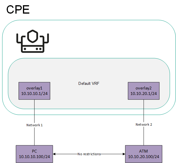
Network interfaces connected to different networks in the virtual default routing and forwarding table
To isolate Network 1 and Network 2, the overlay1 and overlay2 network interfaces must be added to different virtual routing and forwarding tables, which creates two segments (see the figure below).
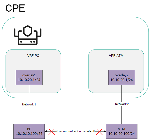
Network interfaces connected to different networks are in separate virtual default routing and forwarding tables
- Sending the 0.0.0.0/0 over BGP.
You can create a separate virtual routing and forwarding table for sending the 0.0.0.0/0 route between devices over BGP. The figure below shows a CPE device with the SD-WAN gateway (GW) role and a standard device. All CPE devices in the network are added to the default virtual routing and forwarding table.
If the SD-WAN gateway sends the 0.0.0.0/0 BGP route from overlay network interface 10.10.10.254/24 to overlay network interface 10.10.10.1/24, such a route cannot be used. This is the case because the default virtual routing and forwarding table already has 0.0.0.0/0 routes with a lower administrative distance for connecting to the controller and orchestrator.
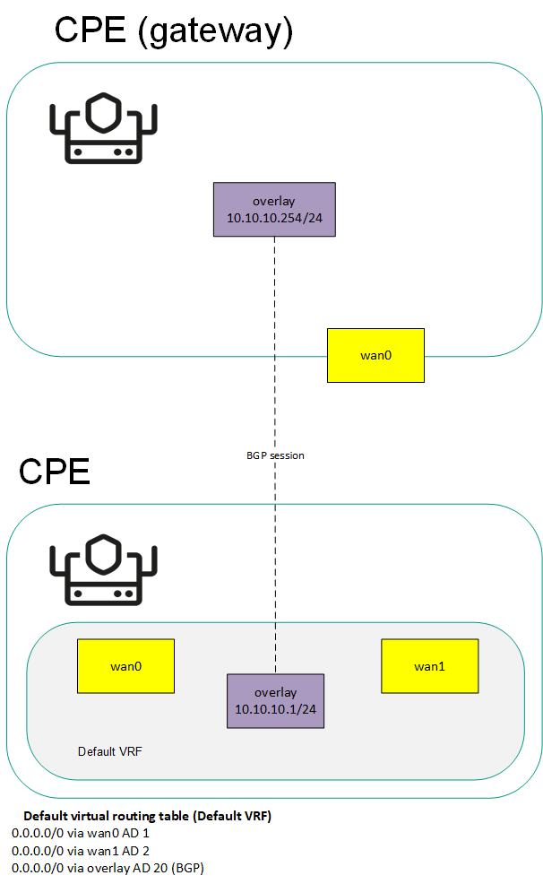
Sending the 0.0.0.0/0 route to a CPE device with the default virtual routing and forwarding table
To send route 0.0.0.0/0 over BGP through the overlay 10.10.10.254/24 network interface to overlay 10.10.10.1/24, you must create a separate table for the overlay 10.10.10.1/24 network interface and add BGP routes to it (see the figure below).
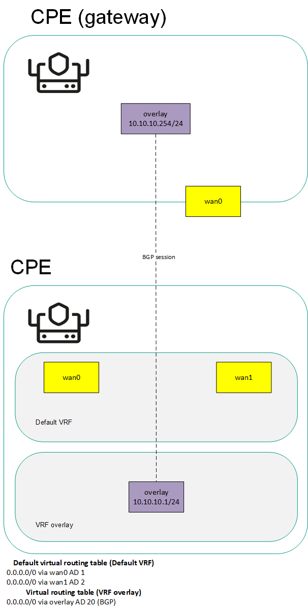
Sending the 0.0.0.0/0 route to a CPE device with a separate virtual routing and forwarding table for BGP routes
The table of virtual routing and forwarding tables is displayed in the CPE template and on the CPE device:
- To display the table of virtual routing and forwarding tables in a CPE template, go to the SD-WAN → CPE templates menu section, click the CPE template, and select the VRF tab.
- To display the table of virtual routing and forwarding tables on a CPE device, go to the SD-WAN → CPE menu section, click the CPE device, and select the VRF tab.
Information about virtual routing and forwarding tables is displayed in the following columns of the table:
- Name is the name of the virtual routing and forwarding table.
- Table is the ID of the virtual routing and forwarding table.
- Interfaces are network interfaces that have been added to the virtual routing and forwarding table.
Creating a virtual routing and forwarding table
You can create a virtual routing and forwarding table in a CPE template or on a CPE device. A virtual routing and forwarding table created in the CPE template is automatically created on all CPE devices that use this CPE template.
To create a virtual routing and forwarding table:
- Create a virtual routing and forwarding table in one of the following ways:
- If you want to create a virtual routing and forwarding table in a CPE template, go to the SD-WAN → CPE templates menu section, click the CPE template, and select the VRF tab.
- If you want to create a virtual routing and forwarding table on a CPE device, go to the SD-WAN → CPE menu section, click the CPE device, and select the VRF tab.
The table of virtual routing and forwarding tables is displayed.
- Click + VRF.
- This opens a window; in that window, in the Name field, enter the name of the virtual routing and forwarding table.
- In the Table field, enter the ID of the virtual routing and forwarding table. Range of values: 100 to 199.
- In the Interfaces drop-down list, select the created network interface that you want to add to the virtual routing and forwarding table. You cannot add the same network interface to multiple virtual routing and forwarding tables.
The network instance is added and displayed in the lower part of the window. You can add multiple network interfaces or delete a network interface. To delete a network interface, click Delete next to it.
If you added a network interface with a name in the 'overlay.<number>' format (for example, 'overlay.100') to the virtual routing and forwarding table, you must select the Enable automatically and Force IP, route, and gateway check boxes when creating or editing the network interface.
- Click + Create.
- Create a record in the orchestrator web interface for the system network interface:
- Select the Network settings tab.
The table of network interfaces is displayed.
- Click + Network interface.
- This opens a window; in that window, in the Alias field, enter the name of the virtual routing and forwarding table that you specified at step 3 of these instructions. Maximum length: 15 characters.
- If firewall zones are assigned to network interfaces in the virtual routing and forwarding table, and the CPE device firewall does not, by default, accept traffic packets forwarded between network interfaces and subnets, in the Zone drop-down list, select a firewall zone. The selected firewall zone must also be assigned to one of the network interfaces in the virtual routing and forwarding table.
- In the Interface name field, enter the name of the virtual routing and forwarding table that you specified at step 3 of these instructions. Maximum length: 256 characters.
- Select the Network settings tab.
- Click Create.
A record for the system network interface is created and displayed in the table.
- In the upper part of the settings area, click Save to save the settings of the CPE template or CPE device.
Modifying the virtual routing and forwarding table
You can edit a virtual routing and forwarding table in a CPE template or on a device. A virtual routing and forwarding table edited in the CPE template is automatically edited on all CPE devices that use this CPE template. You cannot edit a virtual routing and forwarding table that is inherited from a CPE template on a CPE device.
To edit a virtual routing and forwarding table:
- Edit a virtual routing and forwarding table in one of the following ways:
- If you want to edit a virtual routing and forwarding table in a CPE template, go to the SD-WAN → CPE templates menu section, click the CPE template, and select the VRF tab.
- If you want to edit a virtual routing and forwarding table on a CPE device, go to the SD-WAN → CPE menu section, click the CPE device, and select the VRF tab.
The table of virtual routing and forwarding tables is displayed.
- Click Edit next to the virtual routing and forwarding table that you want to edit.
- This opens a window; in that window, if necessary, edit the name and/or ID of the virtual routing and forwarding table, and add or delete network interfaces.
- Click Save.
The virtual routing and forwarding table is modified and updated in the table.
- In the upper part of the settings area, click Save to save the settings of the CPE template or CPE device.
Deleting a virtual routing and forwarding table
You can delete a virtual routing and forwarding table in a CPE template or on a CPE device. A virtual routing and forwarding table deleted in the CPE template is automatically deleted on all CPE devices that use this CPE template. You cannot delete a virtual routing and forwarding table that is inherited from a CPE template on a CPE device.
Deleted virtual routing and forwarding tables cannot be restored.
To delete a virtual routing and forwarding table:
- Delete a virtual routing and forwarding table in one of the following ways:
- If you want to delete a virtual routing and forwarding table in a CPE template, go to the SD-WAN → CPE templates menu section, click the CPE template, and select the VRF tab.
- If you want to delete a virtual routing and forwarding table on a CPE device, go to the SD-WAN → CPE menu section, click the CPE device, and select the VRF tab.
The table of virtual routing and forwarding tables is displayed.
- Click Delete next to the virtual routing and forwarding table that you want to delete.
- In the confirmation window, click Delete.
The virtual routing and forwarding table is deleted and is no longer displayed in the table.
- In the upper part of the settings area, click Save to save the settings of the CPE template or CPE device.
Monitoring traffic packet information using the NetFlow protocol
Kaspersky SD-WAN supports NetFlow versions 1, 5, and 9 for monitoring information about traffic packets on a CPE device.
To avoid configuring each CPE device individually, you can specify basic NetFlow settings in the NetFlow template and then apply the template to CPE devices when adding or manually registering them. If you edit a setting in a NetFlow template, the setting is automatically modified on all CPE devices that are using this NetFlow template. When you edit a setting on a CPE device, that setting becomes independent of the NetFlow template. When the same setting is edited in the NetFlow template, the change is not propagated to the CPE device.
When specifying basic NetFlow settings, you can specify up to four NetFlow collectors. If you want a CPE device to send information about traffic packets to NetFlow collectors, you must enable the NetFlow protocol on network interfaces. The NetFlow protocol can be enabled when creating or editing the network interface.
Managing NetFlow templates
To display the table of NetFlow templates, go to the SD-WAN → NetFlow templates section. One of the NetFlow templates is the default template, which means it is pre-selected when adding and manually registering a CPE device. By default, the Default NetFlow template is created on the administrator portal, which forms the basis for all other NetFlow templates you create. For tenants, you must manually create and assign the default NetFlow template on the self-service portal.
Information about NetFlow templates is displayed in the following columns of the table:
- ID is the ID of the NetFlow template.
- Name is the name of the NetFlow template.
- Usage indicates whether the NetFlow template is being used by CPE devices:
- Yes
- No
- Updated is the date and time when the CPE template settings were last modified.
- User is the name of the user which created the NetFlow template.
- Owner is the tenant to which the NetFlow template belongs.
The actions you can perform with the table are described in the Managing solution component tables instructions.
Creating a NetFlow template
To create a NetFlow template:
- In the menu, go to the SD-WAN → NetFlow templates section.
A table of NetFlow templates is displayed.
- In the upper part of the page, click + NetFlow template.
- This opens a window; in that window, enter the name of the NetFlow template.
- Click Create.
The NetFlow template is created and displayed in the table.
You need to configure the created NetFlow template. For a description of NetFlow template settings, see the instructions on how to configure general NetFlow settings.
Page topSetting a default NetFlow template
You can set a NetFlow template as the default to have it preselected when adding or manually registering a CPE device.
To set a default NetFlow template:
- In the menu, go to the SD-WAN → NetFlow templates section.
A table of NetFlow templates is displayed.
- Click the NetFlow template that you want to make the default NetFlow template.
The settings area is displayed in the lower part of the page. You can expand the settings area to fill the entire page by clicking the expand icon
. - In the upper part of the settings area, under Actions, click Set as default template.
The NetFlow template is set as the default NetFlow template.
Page topExporting a NetFlow template
You can export a NetFlow template to subsequently import it into another NetFlow template.
To export a NetFlow template:
- In the menu, go to the SD-WAN → NetFlow templates section.
A table of NetFlow templates is displayed.
- Click the NetFlow template that you want to export.
The settings area is displayed in the lower part of the page. You can expand the settings area to fill the entire page by clicking the expand icon
. - In the upper part of the settings area, under Actions, click Export.
An archive in the TAR.GZ format is saved on your local device. The archive does not contain information about CPE devices using the NetFlow template.
Page topImporting a NetFlow template
You can export a NetFlow template and subsequently import it into another NetFlow template. NetFlow template settings are specified in accordance with the settings of the imported NetFlow template. During import, you can select the settings that you want to leave unchanged. The NetFlow template into which you are importing another NetFlow template remains applied to CPE devices, but the settings of those CPE devices are not modified.
To import a NetFlow template:
- In the menu, go to the SD-WAN → NetFlow templates section.
A table of NetFlow templates is displayed.
- Click the NetFlow template that you want to export.
The settings area is displayed in the lower part of the page. You can expand the settings area to fill the entire page by clicking the expand icon
. - In the upper part of the settings area, under Actions, click Export.
An archive in the TAR.GZ format is saved on your local device. The archive does not contain information about CPE devices using the NetFlow template.
- Click the NetFlow template into which you want to import another NetFlow template.
The settings area is displayed in the lower part of the page. You can expand the settings area to fill the entire page by clicking the expand icon
. - In the upper part of the settings area, under Actions, click Import.
- This opens a window; in that window, clear the check boxes next to the NetFlow template settings that you want to leave unchanged after import.
- In the File field, specify the path to the TAR.GZ archive.
- Click Import.
NetFlow template settings are modified in accordance with the settings of the imported NetFlow template.
Page topCloning a NetFlow template
You can clone a NetFlow template to create an identical NetFlow template with a different name.
To clone a NetFlow template:
- In the menu, go to the SD-WAN → NetFlow templates section.
A table of NetFlow templates is displayed.
- Click the NetFlow template that you want to clone.
The settings area is displayed in the lower part of the page. You can expand the settings area to fill the entire page by clicking the expand icon
. - In the upper part of the settings area, under Actions, click Clone.
- This opens a window; in that window, enter the name of the new NetFlow template.
- Click Clone.
A copy of the NetFlow template with the new name is created and displayed in the table.
Page topViewing the usage of a NetFlow template
You can see which CPE devices are using the NetFlow template. If a NetFlow template is in use, it cannot be deleted.
To view NetFlow template usage:
- In the menu, go to the SD-WAN → NetFlow templates section.
A table of NetFlow templates is displayed.
- Click the NetFlow template for which you want to view usage information.
The settings area is displayed in the lower part of the page. You can expand the settings area to fill the entire page by clicking the expand icon
. - In the upper part of the settings area, under Actions, click Show usage.
This opens a window with a table of CPE devices that are using the NetFlow template.
Page topDeleting a NetFlow template
You cannot delete a NetFlow template if it is being used by at least one CPE device. You need to look up the usage of the NetFlow template and make sure that it is not in use.
Deleted NetFlow templates cannot be restored.
To delete a NetFlow template:
- In the menu, go to the SD-WAN → NetFlow templates section.
A table of NetFlow templates is displayed.
- Click the NetFlow template that you want to delete.
The settings area is displayed in the lower part of the page. You can expand the settings area to fill the entire page by clicking the expand icon
. - In the upper part of the settings area, under Actions, click Delete.
- In the confirmation window, click Delete.
The NetFlow template is deleted and is no longer displayed in the table.
Page topBasic NetFlow settings
You can specify basic NetFlow settings in a NetFlow template or on a CPE device. Basic NetFlow settings specified in the NetFlow template are automatically propagated to all CPE devices that use this NetFlow template.
To modify the basic NetFlow settings:
- Specify basic NetFlow settings in one of the following ways:
- If you want to edit basic NetFlow settings in a NetFlow template, go to the SD-WAN → NetFlow templates menu section and click the NetFlow template.
- If you want to edit the basic NetFlow settings on a CPE device, go to the SD-WAN → CPE menu section, click the CPE device, select the NetFlow tab, and select the Override check box.
Basic NetFlow settings are displayed.
- In the NetFlow drop-down list, select Enabled. The default value is Disabled.
- Specify the NetFlow collector:
- Under Collectors, click + Add.
- Under Host, enter the IPv4 address of the NetFlow collector.
- Under Port, enter the port number of the NetFlow collector. Range of values: 1 to 65,535.
The NetFlow collector is specified and displayed in the Collectors section. You can specify up to four NetFlow collectors or delete a NetFlow collector. To delete a NetFlow collector, click the delete icon
next to it. - In the Export version drop-down list, select the version of the NetFlow protocol:
- 1
- 5
- 9 (default)
- In the Tracking level drop-down list, select which traffic packet information the CPE device tracks:
- ETHER to track the following information:
- Source and destination IP addresses and ports
- Source and destination MAC addresses
- Outer VLAN tag
- Protocol being used
- FULL to track the source and destination IP addresses and ports, as well as the protocol being used. Default value.
- VLAN to track the following information:
- Source and destination IP addresses and ports
- Outer VLAN tag
- Protocol being used
- PROTO to track the source and destination IP addresses and the protocol being used.
- IP to track the source and destination IP addresses.
- ETHER to track the following information:
- In the Maximum flows field, enter the maximum number of traffic flows that the CPE device can simultaneously track. Range of values: 1 to 65,535. Default value:
8192.The higher the value, the higher the CPU load on the CPE device.
- In the Sampling rate field, specify how frequently the CPE device tracks the traffic packet information. For example, if you enter
10, the CPE device tracks information about every tenth packet of traffic. Range of values: 1 to 8192. Default value:1024.The lower the value, the more accurate the information and the higher the CPU load on the CPE device.
- In the Timeout maximum life (sec.) field, enter the maximum time in seconds for which the CPE device can track traffic flow information. To disable this feature, enter
0. Range of values: 1 to 9999. Default value:60. - In the Hop limit field, enter the maximum number of hops to NetFlow collectors. Range of values: 1 to 255. Default value:
64. - If you want the CPE device to track IPv6 traffic, in the Track IPv6 drop-down list, select Enabled. The default value is Disabled.
- In the upper part of the settings area, click Save to save the settings of the NetFlow template or CPE device.
If you want a CPE device to send information about traffic packets to NetFlow collectors, you must enable the NetFlow protocol on network interfaces. The NetFlow protocol can be enabled when creating or editing the network interface.
Page topChanging the NetFlow template of a CPE Device
To change the NetFlow template of a CPE device:
- In the menu, go to the SD-WAN → CPE section.
A table of CPE devices is displayed.
- Click the CPE device for which you want to change the NetFlow template.
The settings area is displayed in the lower part of the page. You can expand the settings area to fill the entire page by clicking the expand icon
. By default, the Configuration tab is selected, which displays general information about the CPE device. This tab also displays the table of Out-of-band management tasks being performed by the orchestrator. - In the NetFlow template drop-down list, select a created NetFlow template.
- In the upper part of the settings area, click Save to save CPE device settings.
Diagnosing a CPE device
You can request diagnostic information and statistics, such as BGP, OSPF, and PIM protocol usage, from a CPE device. The diagnostic information returned in response to the request is displayed in the web interface of the orchestrator and, if necessary, can be downloaded as a TXT file.
Kaspersky SD-WAN also supports the following utilities for CPE device diagnostics:
- Ping is a utility for testing the connection between a CPE device and a specified IPv4 address. A report with the output of the utility is displayed in the orchestrator web interface.
- Traceroute is a utility for determining the route between a CPE device and a specified IPv4 address. A report with the output of the utility is displayed in the orchestrator web interface.
- Tcpdump is a utility for capturing traffic on a CPE device and writing this traffic to a report file. Capturing means a copy is made of the traffic, and the original traffic is relayed to its destination. The file with the captured traffic can be downloaded or deleted.
- Iperf is a utility for diagnosing network performance and writing the results to a report file. You can use the CPE device as an iperf server or as an iperf client. You can download or delete the network performance diagnostics file.
- Sweep is a utility for performing the following actions on a CPE device:
- Clearing the ARP cache
- Restarting the FRR (Free Range Routing) process
- Clearing the NAT session table
Running an utility is a task that the CPE device receives from the orchestrator; the task obeys the time period configured for the CPE device for sending REST API requests to the orchestrator. If you want the utilities to run sooner, you can enable interactive mode on the CPE device.
In interactive mode, the CPE device uses a shorter interval for sending REST API requests to the orchestrator. Interactive mode ends automatically when the specified duration has passed. You can specify the following interactive mode settings when configuring the connection of a CPE device to the orchestrator and controller:
- The period to wait until the CPE device sends another REST API request to the orchestrator in interactive mode
- The time after which the interactive mode is automatically disabled
Requesting diagnostic information
To request diagnostic information:
- In the menu, go to the SD-WAN → CPE section.
A table of CPE devices is displayed.
- Click the CPE device on which you want to request diagnostic information.
The settings area is displayed in the lower part of the page. You can expand the settings area to fill the entire page by clicking the expand icon
. By default, the Configuration tab is selected, which displays general information about the CPE device. This tab also displays the table of Out-of-band management tasks being performed by the orchestrator. - Select the Diagnostic information tab.
The diagnostic information request parameters are displayed.
- Click Request diagnostic information.
- In the Name drop-down list, select the type of diagnostic information you want to display:
- disk usage for information about the disk usage of the CPE device. Default value.
- dump-flows for information about OpenFlow flows.
- dump-groups for information about OpenFlow groups.
- ip addresses for information about IP addresses assigned to physical ports or virtual interfaces of the operating system of the CPE device.
- vrf data for information about virtual routing and forwarding tables.
- ip neighbors for information about the IP neighbors of the CPE device, obtained from the ARP table or using the Neighbor Discovery Protocol.
- ip routes for information about IPv4 and IPv6 routes.
- ip rules for information about routing rules.
- iptables for information about iptables.
- cpe log for the local log of the CPE device.
- ovs-ofctl show for information about the virtual switch.
- ovs-vsctl show for information about the link between the virtual switch and controllers.
- ovs-vsctl list controller for information about controllers specified for the virtual switch.
- show ip ospf for Information about the OSPF routing process.
- show ip ospf interface for information about OSPF interfaces.
- show ip ospf neighbor - information about OSPF neighbors.
- show ip ospf database for the OSPF database.
- bgp show ip route for information about BGP routes.
- show ip bgp for information about the BGP routing process.
- show ip bgp summary for brief information about the BGP routing process.
- top process for information about Linux processes.
- uptime for information about the CPE device uptime.
- time sync for information about time synchronization on the CPE device using an NTP server.
- netstat for information about network links that the CPE device has established.
- sdwan interfaces for information about SD-WAN interfaces.
- modems for information about modems.
- show bfd peers for information about BFD peers.
- netflow dump-flows for information about NetFlow flows.
- netflow statistics for information about the use of the NetFlow protocol.
- show bfd peers brief for brief information about BFD peers.
- show ip pim bsr for information about the current bootstrap router (BSR).
- show ip pim bsrp-info for information about the group-to-rp mapping received from the boostrap router.
- show ip pim interface for information about PIM interfaces. You can configure the PIM protocol when creating or editing a mutlicast interface.
- show ip pim interface traffic for information about PIM traffic.
- show ip pim join for information about multicast groups to which the CPE device is connected.
- show ip pim neighbor for information about PIM neighbors.
- show ip pim nexthop for information about the next hops of multicast groups.
- show ip pim rp-info for information about rendezvous points. You can specify rendezvous points when specifying basic PIM settings.
- show ip pim secondary for information about the backup PIM router.
- show ip pim state for information about the state of the PIM protocol.
- show ip pim statistics for Information about PIM protocol usage.
- show ip pim upstream for information about PIM sources.
- show ip igmp groups for information about IGMP groups.
- show ip igmp interface for information about IGMP interfaces. You can configure IGMP when creating or editing a mutlicast interface.
- show ip igmp interface detail for detailed information about IGMP interfaces.
- show ip igmp sources for information about IGMP sources.
- igmp statistics for information about IGMP usage.
- show ip multicast for information about the multicast routing process.
- show ip mroute for information about multicast routes.
- show ip mroute summary for brief information about multicast routes.
- vswitchd log for the log of the ovs-vswitchd process.
- firewall config for information about the firewall.
- sw version for the firmware version of the CPE device.
- vrrp stats for brief information about VRRP usage.
- vrrp data for information about VRRP usage.
- If you want to filter the displayed diagnostic information:
- In the Find line by pattern field, enter words that must be found in the lines of diagnostic information that you want to be displayed. Maximum length: 64 characters. If you want to display only lines that do not contain the words you entered, select the Select non-matching lines check box. This check box is cleared by default.
- In the Print N lines before and after field, enter the number of blank lines you want to display before and after each line of diagnostic information.
- If you want to download the file with diagnostic information, click Download file with latest data.
An TXT file is saved on your local device.
Enabling interactive mode
You can specify the following interactive mode settings when configuring the connection of a CPE device to the orchestrator and controller:
- The period to wait until the CPE device sends another REST API request to the orchestrator in interactive mode
- The time after which the interactive mode is automatically disabled
To enable interactive mode:
- In the menu, go to the SD-WAN → CPE section.
A table of CPE devices is displayed.
- Click the CPE device on which you want to enable interactive mode.
The settings area is displayed in the lower part of the page. You can expand the settings area to fill the entire page by clicking the expand icon
. By default, the Configuration tab is selected, which displays general information about the CPE device. This tab also displays the table of Out-of-band management tasks being performed by the orchestrator. - In the upper part of the settings area, click Enable interactive.
Interactive mode is enabled on the CPE device.
Page topRunning the ping utility
To run the ping utility:
- In the menu, go to the SD-WAN → CPE section.
A table of CPE devices is displayed.
- Click the CPE device on which you want to run the ping utility.
The settings area is displayed in the lower part of the page. You can expand the settings area to fill the entire page by clicking the expand icon
. By default, the Configuration tab is selected, which displays general information about the CPE device. This tab also displays the table of Out-of-band management tasks being performed by the orchestrator. - Select the Utilities tab.
By default, the Ping tab is selected, which displays the ping utility settings.
- In the Destination IP address field, enter the IPv4 address to which you the CPE device sends ICMP requests.
- If you want the CPE device to send ICMP requests from a certain created network interface, in the Source interface drop-down list, select the network interface.
- In the Count field, enter the number of ICMP requests that the CPE device sends. Range of values: 1 to 1,000,000. Default value:
5. - In the Timeout (sec.) field, enter the time in seconds after which the CPE device must receive an ICMP response to consider the request a success. Range of values: 1 to 3600. Default value:
2. - In the Size field, enter the size of the ICMP request in bytes. Range of values: 1 to 65,535. The default value is
56. - In the TTL field, enter the maximum number of hops for ICMP requests. Range of values: 1 to 255. Default value:
255. - In the Interval field, enter the interval in seconds for the CPE device to use when sending ICMP requests to the specified IPv4 address. Range of values: 1 to 300. Default value:
1. - Click Run.
The ping utility is run on the CPE device, and a report containing the output of the ping utility is displayed in the lower part of the settings area.
Page topRunning the traceroute utility
To run the traceroute utility:
- In the menu, go to the SD-WAN → CPE section.
A table of CPE devices is displayed.
- Click the CPE device on which you want to run the traceroute utility.
The settings area is displayed in the lower part of the page. You can expand the settings area to fill the entire page by clicking the expand icon
. By default, the Configuration tab is selected, which displays general information about the CPE device. This tab also displays the table of Out-of-band management tasks being performed by the orchestrator. - Select the Utilities → Traceroute tab.
The traceroute utility settings are displayed.
- In the Destination IP address field, enter the IPv4 address to which you the CPE device sends the series of ICMP requests.
- If you want the CPE device to send the series of ICMP requests from a certain created network interface, in the Source interface drop-down list, select the network interface.
- If you want the CPE device to use the DNS server to resolve IP addresses to domain names when creating the report with the output of the traceroute utility, select the Resolve DNS names check box. You can specify a DNS server when creating or editing a network interface. IP addresses that cannot be resolved to domain names are also displayed in the report. This check box is cleared by default.
- In the Probes timeout (sec.) field, enter the time in seconds after which the CPE device must receive a series of ICMP responses to consider the series of ICMP requests a success. Range of values: 1 to 30. Default value:
3. - In the Max hops field, enter the maximum number of hops for the series of ICMP requests. Range of values: 1 to 60. Default value:
10. - Click Run.
The traceroute utility is run on the CPE device, and a report containing the output of the traceroute utility is displayed in the lower part of the settings area.
Page topRunning the tcpdump utility
If you have previously run the tcpdump utility, a report file was generated with the captured traffic. When you run the utility again, that report file is overwritten. You can download the previous report file if you want to keep it.
The tcpdump utility puts additional load on the CPU of the CPE device.
To run the tcpdump utility:
- In the menu, go to the SD-WAN → CPE section.
A table of CPE devices is displayed.
- Click the CPE device on which you want to run the tcpdump utility.
The settings area is displayed in the lower part of the page. You can expand the settings area to fill the entire page by clicking the expand icon
. By default, the Configuration tab is selected, which displays general information about the CPE device. This tab also displays the table of Out-of-band management tasks being performed by the orchestrator. - Select the Utilities → Tcpdump tab.
The tcpdump utility settings are displayed.
- In the Capture interface drop-down list, select the created network interface on which you want to capture traffic.
- In the Direction drop-down list, select the direction of the traffic you want to capture:
- in to capture incoming traffic.
- out to capture outgoing traffic.
- in/out to capture both incoming and outgoing traffic. Default value.
- If you want the CPE device to use the DNS server to resolve IP addresses to domain names when creating the report file with the captured traffic, select the Resolve DNS names check box. You can specify a DNS server when creating or editing a network interface. IP addresses that cannot be resolved to domain names are also reflected in the report file. This check box is cleared by default.
- If you want to use a filter to capture traffic, in the Capture expression (tcpdump filter format) field, enter the syntax of the filter. Maximum length: 1024 characters. For example, you can use the following filters:
icmpto capture only ICMP traffic packets.host 1.2.3.4 and (port 80 or 443)to capture only traffic packets with IPv4 address 1.2.3.4 and source or destination TCP port 80 or 443.tcp[13] & 2 != 0to capture only TCP SYN traffic packets.
Detailed information about traffic filters can be obtained from the official tcpdump documentation.
- In the Maximum capture time (sec.) field, enter the time in seconds after which traffic capture stops. Range of values: 10 to 600. Default value:
30. - In the Max. captured packets field, enter the number of traffic packets that you want collected before traffic capture stops. Range of values: 1 to 10,000. Default value:
1000.Traffic capturing stops when the time specified in the Maximum capture time (sec.) field passes, or when the number of traffic packets specified in the Max. captured packets field is captured.
- Click Run.
The tcpdump utility is run on the CPE device, and a report file with the captured traffic is generated.
Page topRunning the iperf utility
If you have already run the iperf utility, a report file was generated with network performance diagnostics results. When you run the utility again, that report file is overwritten. You can download the previous report file if you want to keep it.
To run the iperf utility:
- In the menu, go to the SD-WAN → CPE section.
A table of CPE devices is displayed.
- Click the CPE device on which you want to run the iperf utility.
The settings area is displayed in the lower part of the page. You can expand the settings area to fill the entire page by clicking the expand icon
. By default, the Configuration tab is selected, which displays general information about the CPE device. This tab also displays the table of Out-of-band management tasks being performed by the orchestrator. - Select the Utilities → Iperf tab.
The iperf utility settings are displayed.
- Specify the mode in which you want to use the iperf utility on the CPE device by selecting one of the following options:
- Server to use the CPE device as an iperf server.
- Client to use the CPE device as an iperf client.
- If you chose the Server option, configure the iperf server:
- In the Port field, enter the TCP or UDP port number of the iperf server. Range of values: 1001 to 65,535. Default value:
7777. - In the Report interval (sec.) field, enter the interval in seconds for writing lines to the report file. Range of values: 0 to 60. Default value:
3. - If you do not want to create a report file with network performance diagnostics results, select the Do not report check box. This check box is cleared by default.
- Under Report format, select the format of the network performance diagnostics results in the report file:
- Kbit/sec (default)
- Mbit/sec
- Kbyte/sec
- Mbyte/sec
- In the Run server for (sec.) field, enter the duration in seconds for which you want the iperf server to run. Range of values: 60 to 3600. Default value:
300.
- In the Port field, enter the TCP or UDP port number of the iperf server. Range of values: 1001 to 65,535. Default value:
- If you chose the Client option, configure the iperf client:
- In the Server IP field, enter the IPv4 address of the iperf server to which the client connects.
- In the Port field, enter the TCP or UDP port number of the iperf server to which the client connects. Range of values: 1001 to 65,535. Default value:
7777. - In the Report interval (sec.) field, enter the interval in seconds for writing lines to the performance diagnostics report file. Range of values: 0 to 60. Default value:
3. - If you do not want to create a report file with network performance diagnostics results, select the Do not report check box. This check box is cleared by default.
- Under Report format, select the format of the network performance diagnostics results in the report file:
- Kbit/sec (default)
- Mbit/sec
- Kbyte/sec
- Mbyte/sec
- In the Run client for (sec.) field, enter the duration in seconds for which you want the iperf client to run. Range of values: 60 to 3600. Default value:
60. - Specify the port type of the iperf server by selecting one of the following options:
- TCP (default).
- UDP
- In the Client bitrate field, enter the bit rate of the iperf client in one of the following formats:
<bit rate in kbps>kor<bit rate in kbps>KFor example, if you enter
10000K, the bit rate is 10,000 kbps.<bit rate in Mbps>mor<bit rate in Mbps>MFor example, if you enter
10M, the bit rate is 10 Mbps.
- In the Test direction drop-down list, select the direction of traffic that you want to use for measuring network performance:
- client-server to use the traffic that the iperf client sends to the server. Default value.
- server-client to use the traffic that the iperf server sends to the client.
- bidirectional to use traffic that the iperf client sends to the server as well as the traffic that the iperf server sends to the client.
- If necessary, in the TCP windows size, bytes field, enter the TCP window size in bytes. If you do not specify a value for this parameter, the TCP window size is automatically detected.
- If necessary, in the TCP MSS, bytes field, enter the maximum TCP segment size in bytes.
- Click Run.
The iperf utility is run on the CPE device, and a report file with the network diagnostics results is generated.
To manage the report file, click Download results.
Page topRunning the sweep utility
You can use the sweep utility to clear the ARP cache, restart the Free Range Routing (FRR) process, and/or clear the NAT session table on a CPE device.
Restarting the FRR process and clearing the NAT session table may cause traffic transmission to stop for a few seconds.
To run the sweep utility:
- In the menu, go to the SD-WAN → CPE section.
A table of CPE devices is displayed.
- Click the CPE device on which you want to run the sweep utility.
The settings area is displayed in the lower part of the page. You can expand the settings area to fill the entire page by clicking the expand icon
. By default, the Configuration tab is selected, which displays general information about the CPE device. This tab also displays the table of Out-of-band management tasks being performed by the orchestrator. - Select the Utilities → Sweep tab.
The sweep utility settings are displayed.
- If you want to clear the ARP cache:
- Under Clear ARP-cache on interface, select the created network interface on which you want to clear the ARP cache. If you want to clear the ARP cache on all network interfaces, select All.
- Click Run.
The ARP cache is cleared on the CPE device.
- If you want to restart the FRR process, under Restart FRR (routing) process, click Run.
The FRR process is restarted on the CPE device.
- If you want to clear the NAT session table, under Clear NAT sessions table, click Run. You can configure NAT on a CPE device using a firewall.
The NAT session table is cleared on the CPE device.
Managing report files
Report files are generated from the output of the tcpdump and iperf utilities. To display the table of report files on a CPE device, go to the SD-WAN → CPE menu section, click the CPE device, and select the Utilities → Files tab. Information about report files is displayed in the following columns of the table:
- Type is the type of the report file.
- Created is the date and time when the report file was created.
The actions you can perform with the table are described in the Managing solution component tables instructions.
Downloading a report file
To download a report file:
- In the menu, go to the SD-WAN → CPE section.
A table of CPE devices is displayed.
- Click the CPE device from which you want to download the report file.
The settings area is displayed in the lower part of the page. You can expand the settings area to fill the entire page by clicking the expand icon
. By default, the Configuration tab is selected, which displays general information about the CPE device. This tab also displays the table of Out-of-band management tasks being performed by the orchestrator. - Select the Utilities → Files tab.
A table of report files is displayed.
- Click Download file next to the report file that you want to download.
An TXT file is saved on your local device.
Page topDeleting a report file
Deleted report files cannot be restored.
To delete a report file:
- In the menu, go to the SD-WAN → CPE section.
A table of CPE devices is displayed.
- Click the CPE device on which you want to delete a report file.
The settings area is displayed in the lower part of the page. You can expand the settings area to fill the entire page by clicking the expand icon
. By default, the Configuration tab is selected, which displays general information about the CPE device. This tab also displays the table of Out-of-band management tasks being performed by the orchestrator. - Select the Utilities → Files tab.
A table of report files is displayed.
- Click Delete next to the report file that you want to delete.
- In the confirmation window, click Delete.
The report file is deleted and is no longer displayed in the table.
Page topRunning scheduled tasks on CPE devices
Kaspersky SD-WAN supports running scheduled tasks on CPE devices. Unlike standard tasks, scheduled tasks run at a specified time instead of immediately. You can use tags to group CPE devices on which you want to run a scheduled task.
Two types of scheduled tasks exist:
- Scheduling scripts on CPE devices.
- Scheduling firmware updates on manually selected CPE devices and on CPE devices with specified tags.
When you create a scheduled task, it uses the time zone of the virtual machine on which the orchestrator is deployed. For example, if you schedule a script to run on a CPE device at 2:00 p.m., the script runs at 2:00 p.m. in the time zone of the orchestrator, even if the time on the CPE device is 6:00 p.m.
We recommend taking into account the following special considerations when managing scheduled tasks:
- A 10-second inaccuracy is considered acceptable for the moment when the scheduled task is run.
- If multiple scheduled tasks exist, they run simultaneously. If the orchestrator cannot run all scheduled tasks simultaneously, they are run in the order they were created.
- Deleting a CPE template automatically deletes all scheduled tasks associated with it.
- Deleting a CPE device automatically deletes all scheduled tasks associated with it.
- When deleting a script associated with scheduled tasks, this action requires additional confirmation. If you confirm the action, the script is deleted and cannot be run within the created scheduled tasks.
You can manually run scheduled tasks that have not yet been run.
The table of scheduled tasks is displayed in the Scheduler section. Information about scheduled tasks is displayed in the following columns of the table:
- ID is the ID of the scheduled task.
- Name is the name of the scheduled task.
- User is the name of the user which created the scheduled task.
- Created is the date and time when the scheduled task was created.
- Status is the status of the scheduled task:
- Done means the scheduled task has been completed successfully.
- Error means an error occurred while running the scheduled task.
- Pending means the scheduled task is placed in the orchestrator database and is awaiting execution.
- Queued means the scheduled task is queued for execution.
- Running means the scheduled task is running.
- Scheduled is the date and time when the scheduled task was run.
The actions that you can perform with the table are described in the Managing solution component tables instructions.
Creating a scheduled task
To create a scheduled task:
- In the menu, go to the Scheduler section.
The table of scheduled tasks is displayed.
- In the upper part of the page, click + Delayed task.
- Specify the settings of the scheduled task. For a description of scheduled task settings, see the following instructions:
- Click Create.
The scheduled task is created and displayed in the table.
Page topManually running a scheduled task
To manually run a scheduled task:
- In the menu, go to the Scheduler section.
The table of scheduled tasks is displayed.
- To manually run an individual scheduled task:
- Click the scheduled task that you want to manually run.
The settings area is displayed in the lower part of the page. You can expand the settings area to fill the entire page by clicking the expand icon
. - In the upper part of the settings area, under Actions, click Run now.
- Click the scheduled task that you want to manually run.
- To manually run multiple scheduled tasks:
- Select check boxes next to scheduled tasks that you want to manually run.
- In the upper part of the table, click Actions → Run now.
- In the confirmation window, click Run now.
The scheduled tasks are completed, and their status in the Status column changes to Done.
Page topDeleting a scheduled task
Deleted scheduled tasks cannot be restored.
To delete a scheduled task:
- In the menu, go to the Scheduler section.
The table of scheduled tasks is displayed.
- To delete an individual scheduled task:
- Click the scheduled task that you want to delete.
The settings area is displayed in the lower part of the page. You can expand the settings area to fill the entire page by clicking the expand icon
. - In the upper part of the settings area, under Actions, click Delete.
- Click the scheduled task that you want to delete.
- To delete multiple scheduled tasks:
- Select check boxes next to scheduled tasks that you want to delete.
- In the upper part of the table, click Actions → Delete.
- In the confirmation window, click Delete.
The scheduled tasks are deleted and are no longer displayed in the table.
Page top